Appendix B - Settings and Signals
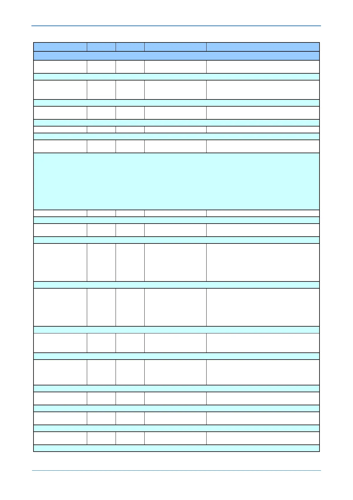
MENU TEXT COL ROW DEFAULT SETTING AVAILABLE OPTIONS
DESCRIPTION
ISEF> Char Angle 3A 59 90
From -95 to 95 in steps of 1
[Courier Number (angle)]
Setting for the IED characteristic angle used for the directional decision.
ISEF>VNpol Input 3A 5A Derived
Derived
Setting determines which will be selected as the input source of polarizing voltage for directional decision, 'derived' or 'measured'.
ISEF> VNpol Set 3A 5B 5
From 0.5*V1 to 88*V1 in steps of 0.5*V1
[Courier Number (voltage)]
Setting for the minimum zero sequence voltage polarizing quantity required for directional decision.
PN> Setting 3A 5E 9
From 0.0*V1*I3 to 20*V1*I3 in steps of 0.05*V1*I3
[Courier Number (power Watts)]
Setting for the threshold for the wattmetric component of zero sequence power. The power calculation is as follows:
The PN> setting corresponds to:
Vres x Ires x Cos (φ – φc) = 9 x Vo x Io x Cos (φ– φc)
Where; φ = Angle between the Polarizing Voltage (-Vres) and the Residual Current
φc = IED Characteristic Angle (RCA) Setting (ISEF> Char Angle)
Vres = Residual Voltage
Ires = Residual Current
Vo = Zero Sequence Voltage
Io = Zero Sequence Current
IREF> Is 3A 65 0.2
From 0.05*I3 to 1.0*I3 in steps of 0.01*I3
[Courier Number (current)]
Pick-up setting for the High Impedance restricted earth fault element.
ISEF>1 UsrRstChr 3A 70 DT
Default Curve 1
Default Curve 2
Default Curve 3
Default Curve 4
Setting to determine the type of reset/release characteristic of the user defined curves.
ISEF>2 UsrRstChr 3A 75 DT
Default Curve 1
Default Curve 2
Default Curve 3
Default Curve 4
Setting to determine the type of reset/release characteristic of the user defined curves.
VN Input 3B 01 Derived
Derived
Setting determines which will be selected as the input source of residual voltage for signal input, 'derived' or 'measured'.
VN>1 Function 3B 02 DT
DT
IDMT
[Indexed String]
Setting for the tripping characteristic of the first stage residual overvoltage element.
VN>1 Voltage Set 3B 03 5
From 1*V1 to 80*V1 in steps of 1*V1
[Courier Number (voltage)]
Pick-up setting for the first stage residual overvoltage characteristic.
VN>1 Time Delay 3B 04 5
From 0 to 100 in steps of 0.01
[Courier Number (time-seconds)]
Operating time delay setting for the first stage definite time residual overvoltage element.
VN>1 TMS 3B 05 1
From 0.5 to 100 in steps of 0.5
[Courier Number (Decimal)]
Setting for the time multiplier setting to adjust the operating time of the IDMT characteristic.