Appendix B - Settings and Signals
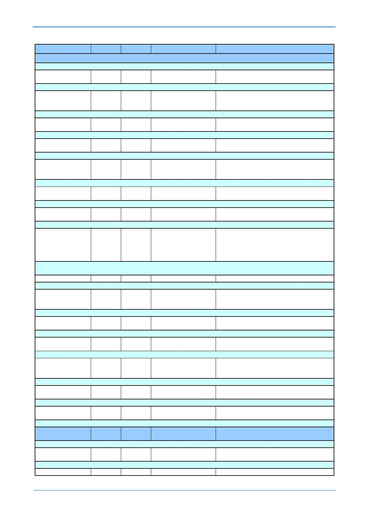
MENU TEXT COL ROW DEFAULT SETTING AVAILABLE OPTIONS
DESCRIPTION
Setting that determines the pick-up threshold for the second stage underfrequency element.
F<2 Time Delay 43 07 3
From 0 to 100 in steps of 0.01
[Courier Number (time-seconds)]
Setting that determines the minimum operating time-delay for the second stage underfrequency element.
F<3 Status 43 08 Disabled
Enabled
Setting to enable or disable the third stage underfrequency element.
F<3 Setting 43 09 48.5
From 45 to 65 in steps of 0.01
[Courier Number (frequency)]
Setting that determines the pick-up threshold for the third stage underfrequency element.
F<3 Time Delay 43 0A 2
From 0 to 100 in steps of 0.01
[Courier Number (time-seconds)]
Setting that determines the minimum operating time-delay for the third stage underfrequency element.
F<4 Status 43 0B Disabled
Enabled
Setting to enable or disable the fourth stage underfrequency element.
F<4 Setting 43 0C 48
From 45 to 65 in steps of 0.01
[Courier Number (frequency)]
Setting that determines the pick-up threshold for the fourth stage underfrequency element.
F<4 Time Delay 43 0D 1
From 0 to 100 in steps of 0.01
[Courier Number (time-seconds)]
Setting that determines the minimum operating time-delay for the fourth stage underfrequency element.
F< Function Link 43 0E 0x0
F<2 U/V Block
F<3 U/V Block
F<4 U/V Block
Settings that determines whether undervoltage level (setting CB FAIL & P.DEAD/POLEDEAD VOLTAGE/V< ) signal block the underfrequency
elements.
Over Frequency Sub Heading
F>1 Status 43 10 Enabled
Enabled
Setting to enable or disable the first stage overfrequency element.
F>1 Setting 43 11 50.5
From 45 to 65 in steps of 0.01
[Courier Number (frequency)]
Setting that determines the pick-up threshold for the first stage overfrequency element.
F>1 Time Delay 43 12 2
From 0 to 100 in steps of 0.01
[Courier Number (time-seconds)]
Setting that determines the minimum operating time-delay for the first stage overfrequency element.
F>2 Status 43 13 Disabled
Enabled
Setting to enable or disable the second stage overfrequency element.
F>2 Setting 43 14 51
From 45 to 65 in steps of 0.01
[Courier Number (frequency)]
Setting that determines the pick-up threshold for the second stage overfrequency element.
F>2 Time Delay 43 15 1
From 0 to 100 in steps of 0.01
[Courier Number (time-seconds)]
Setting that determines the minimum operating time-delay for the second stage overfrequency element.
GROUP 1: DF/DT
PROTECTION
44 00
This column contains settings for rate of change of Frequency
df/dt Avg.Cycles 44 01 6
6 or 12
[Unsigned Integer (16 bits)]
This setting is available for calculating the rate of change of frequency measurement over a fixed period of either 6 or 12 cycles.