2 Installation
K0443 Revision A 2 - 10 [EN] English
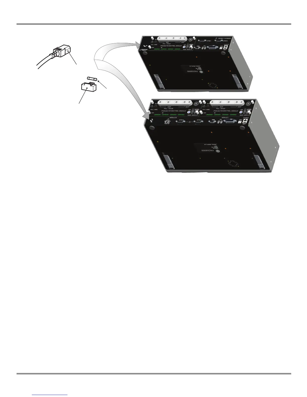
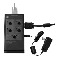
Figure 2-7 Electrical Connections
Pressure Control Module Input and Output Connectors
24V DC Output @ 100mA maximum
An integral self-resetting fuse protects this output.
Logic (switch) Input
This facility can be used to trigger the instrument from a pressure switch contact during the
Pressure Switch Task (Ref Section 3.4, Control Mode).
Connections are not polarised and can be connected either way. Integral opto-isolators
protect this input circuit.
This facility can be energised by external SELV compliant equipment.
4-way connector: pin “+” = +24 Vdc
pin “-” = 0 Vdc
4-way connector: Input
Output
1 IEC power connector
2 Fuse carrier
3 Fuse