Do you have a question about the GE PACE5000 and is the answer not in the manual?
Advises against applying pressures greater than the maximum working pressure.
States that no toxic materials are used in the equipment's construction.
Lists display, EMC, electrical, power, and pressure safety details.
Specifies operating environment, temperature, humidity, and altitude.
Lists related manuals and explains safety and warning symbols.
Key warnings for safe operation and maintenance regarding pressure and electrical safety.
Provides factors for converting between various pressure units.
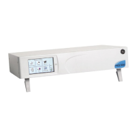
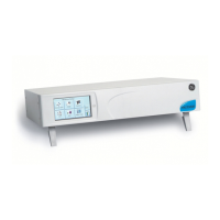
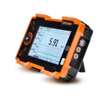
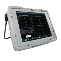
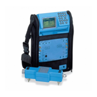
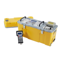
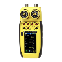
Introduces the instruments and their touch-screen capabilities.
Contents of packaging and steps before initial operation.
Specifies thread types and safety warnings for pneumatic connections.
Details ports and requirements for clean, dry gas supply.
Safety responsibilities and pressure module placement guidelines.
Equipment for supply and illustrations of pneumatic connections.
Steps and considerations for mounting the instrument in a rack.
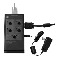
Critical electrical safety warnings and power connection procedures.
Details for RS232, IEEE 488, and Ethernet ports.
Steps required before operating the instrument.
Procedure from power on to entering measure mode, including self-test.
Key displays and icons used in measure mode.
Configuring pressure zero, process, filter, tare, task, and units.
How to enter control mode and interpret its display.
Configuring vent rate, nudge resolution, limits, slew rate, and control modes.
Functionality in different modes and introduction to tasks.
Steps to execute tasks like pressure control and venting.
Configuring test sequences and viewing an example.
Setting up and applying individual set-point values.
Access to supervisor, calibration, and save/recall settings.
Details shown in the status area for various parameters.
How the option enables absolute/gauge pressure selection.
PIN protection, venting, limits, alarms, and communication configuration.
Details on hardware, software, history, and communications status.
Routine tasks, inspection procedures, cleaning, and testing.
Instrument calibration process and replacement parts list.
Procedures for accessing and replacing module filters.
Steps for replacing the pressure module.
Procedure to verify instrument functionality and serviceability.
Troubleshooting table for common faults and approved service contacts.
Guidelines for pressure supply, gas type, and conditioning.
Alert displayed when the maximum pressure limit is exceeded.
Requirements for gas purity and the need for vacuum supply.
Using in-line filters to protect the instrument from contamination.
Setup and protection guidelines for vacuum pumps.
How to vent pressure, use the output port, and reference port.
Explanation of visual indicators used in set-up menus.
Configuring pressure zero, process, filter, tare, task, and units.
Configuring vent rate, nudge resolution, limits, slew rate, and control modes.
Access to supervisor, calibration, and save/recall settings.
PIN protection, venting, limits, alarms, and communication configuration.
Connector, protocol, and configuration information for communication ports.
USB connection details, communication modes, and timeout settings.
Managing idle timeout behavior and height difference corrections.
Controlling task access and changing the supervisor PIN.
Customizing units and assigning instrument names.
List of available languages and procedure for adding new ones.
Steps to activate software options using a calibration PIN.
Procedure for performing leak tests on connected systems.
Procedures for connecting and testing pressure switches.
Creating and running custom test programs.
Detailed explanations of commands used in test programs.
A step-by-step illustration of a test program.
Techniques for creating repetitive test sequences using GOTO/COUNT.
Visual representation of pressure range selection with the option.
Introduction to the specialized aeronautical application.
Safety and procedures for leak testing aeronautical components.
How the instrument generates altitude and airspeed parameters.
Safety notes for aeronautical testing, including rates of change.
Converting units and setting reference pressure for aeronautical data.
How modules work together and parameters displayed in aeronautical mode.
Configuring selectable voltage and current output ranges.
Configuring trigger conditions and understanding relay specifications.
Accessing calibration settings and changing the PIN.
Steps for returning the unit and obtaining authorizations.
Steps before packaging and choosing materials, sealing, and marking.
List of typical parts and their part numbers for vacuum systems.
| Model | PACE5000 |
|---|---|
| Category | Test Equipment |
| Manufacturer | GE |
| Test Functions | Pressure calibration, pressure control, pressure measurement |
| Calibration | Field or lab calibration |
| Communication | RS-232 |