2 Installation
K0443 Revision A 2 - 12 [EN] English
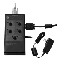
RS232 Interface
When using the RS232 interface, a cable must be connected directly from the instrument to
a suitable port on the computer in a ‘point to point’ link. The pin connections for the 9-pin D-
type, RS232 connector and the relationship between the instrument and the RS232 control
signals, together with device interconnection interface is shown in Table 2-1. The instrument
is configured as Data Circuit Terminating Equipment (DCE).
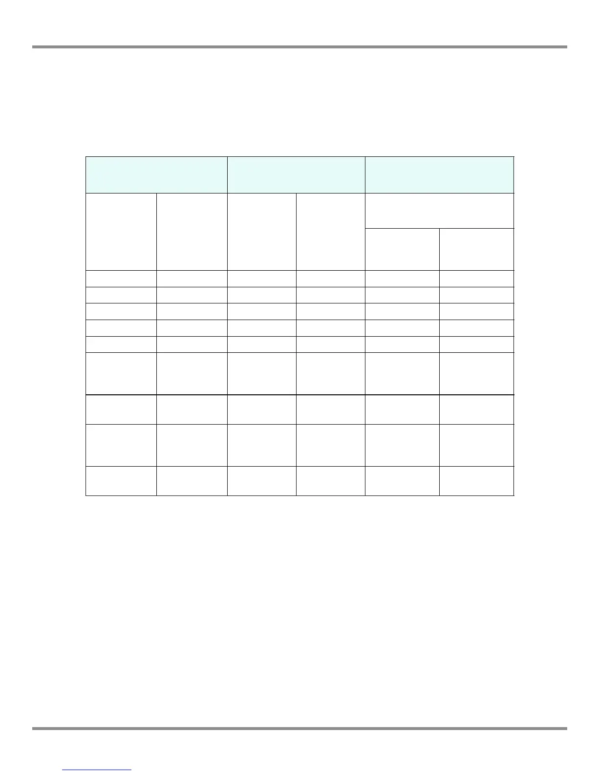
Table 2-1, RS232 Connections
Handshaking connections
Instrument Control Line Computer/Printer
Instrument
Function
Connector
9-way
D-type
Pin No.
Signal
Direction
RS232
Terminology
Connector Type
9-way
D-type
Pin No.
25-way
D-type
Pin No.
RxD (I/P) 3 TxD 3 2
TxD (O/P) 2 RxD 2 3
GND 5 GND 5 7
CTS (I/P) 7 RTS 7 4
RTS (O/P) 8 CTS 8 5
Pulled
high
internally
1
RLSD
(DCD)
18
Not
connected
4 DTR 4 20
Pulled
high
internally
6
DSR
DCE Ready
66
Equipment
chassis
Connector
shell
Cable Screen - 1
Software handshaking use: TXD, RXD and GND.
Hardware handshaking use: TXD, RXD, GND, CTS, RTS and DTR.