PACE Pressure Controller User Manual
[EN] English 2 - 3 K0443 Revision A
Refer to the data sheet for a complete range of adaptors.
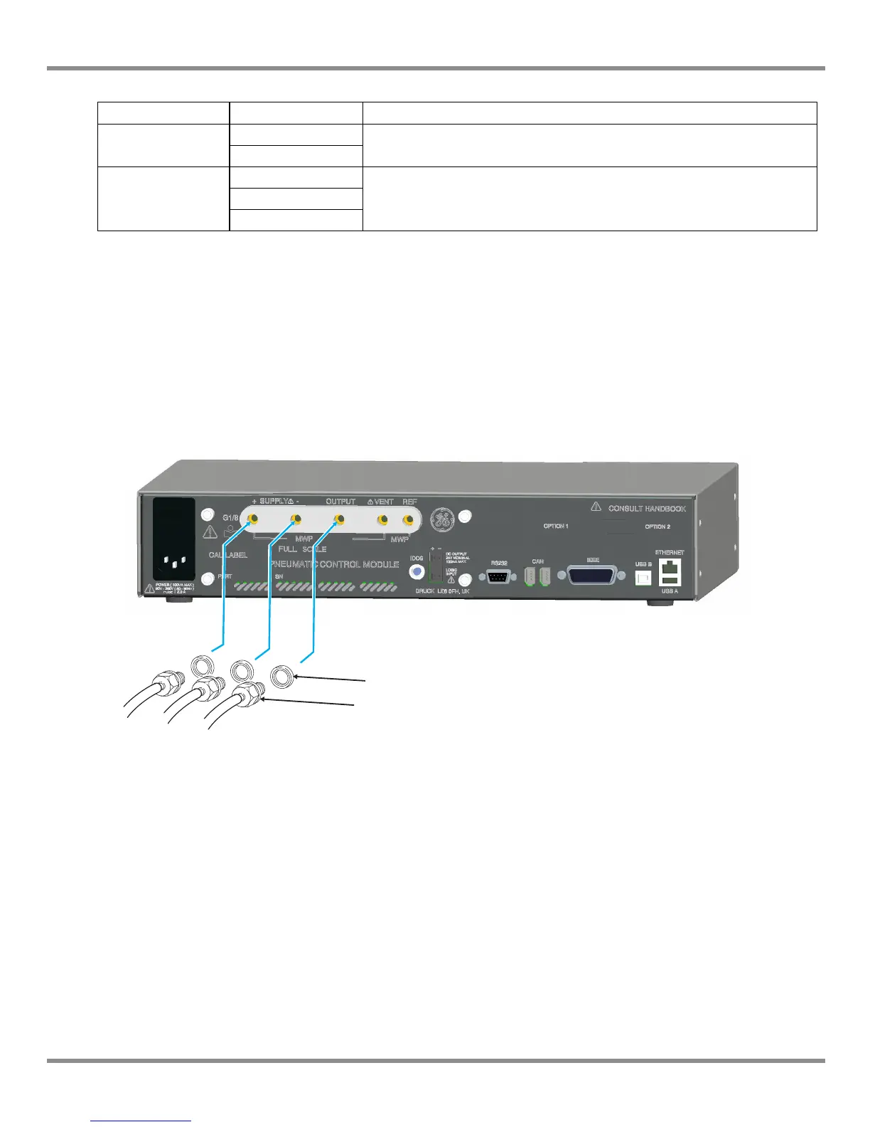
Pressure supply (Ref: Figure 2-1, Pneumatic connections)
1. The pressure supply must be clean, dry gas, nitrogen or air and at the correct pressure,
(Ref: Section 6, Reference and Specification).
2. Make sure the user systems can be isolated and vented.
3. Connect pressure and vacuum supplies to the SUPPLY + and SUPPLY - connection
ports.
4. Connect the Unit Under Test (UUT) to the required output connection port.
Figure 2-1, Pneumatic Connections
Note: For systems requiring NPT connections, please order optional NPT adaptors.
Connection Port
Input
supply +
ISO228/1 G 1/8 parallel threads (DIN ISO228/1, JIS B0202)
supply -
Output
Output
ISO228/1 G 1/8 parallel threads (DIN ISO228/1, JIS B0202)Vent
Reference