GE
D
IRECTION GB091046, REVISION 2 VIVID E9 / VIVID E7 BT’13 SERVICE MANUAL
Chapter 8 - Replacement procedures 8 - 255
8-11-5-2 Front Module removal procedure
Follow these steps to remove the Front Module:
1.) Place the BEP on a table for better access (and ergonomics).
2.) Remove the BEP Cover.
a.) Loosen the BEP Cover’s fixing screw(s).
- On BEP6 there are two finger screws on the top of the BEP Cover.
b.) Tilt the top of the BEP Cover away from the BEP.
c.) Set the BEP Cover aside.
3.) Remove the Graphics Adapter to get better access.
4.) Disconnect the Front Module Cable from the motherboard.
NOTE: See 8-11-3 "Hard Disk Drive (HDD) replacement" on page 8-241 for more information.
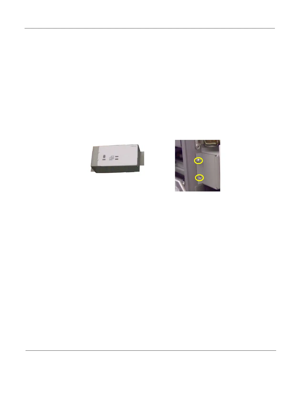
5.) Remove the two screws securing the Front Module to the BEP frame.
6.) Remove the Front Module.
Figure 8-195 Front Module screw placement