GE
D
IRECTION GB091046, REVISION 2 VIVID E9 / VIVID E7 BT’13 SERVICE MANUAL
8 - 256 Section 8-11 - Back End Processor (BEP) parts replacement
8-11-5-3 Front Module installation procedure
Follow these steps to install the Front Module:
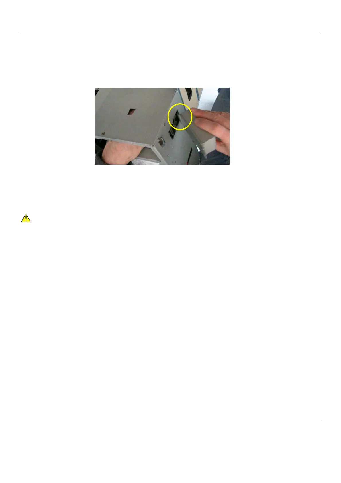
1.) Install the Front Module into the BEP frame. Be sure the Front Module lip slides into the Module
opening.
2.) Install the two screws securing the Front Module to the BEP frame.
3.) Connect the Front Module Cable to the connector on the motherboard.
4.) Install the BEP Cover as described in these steps:
a.) Insert the base of the BEP Cover inside the base of the BEP.
Be sure the bottom lip of the BEP Cover rests inside the BEP.
b.) Tilt the top of the BEP Cover toward the VIVID E9 / VIVID E7.
c.) Install the fixing screw(s) for the BEP Cover:
- On BEP6 there are two finger screws on the top of the BEP Cover.
5.) Replace the Side Cover.
6.) Install the BEP.
7.) Connect the Mains Power Cable to the wall outlet.
8.) Power up the VIVID E9 / VIVID E7.
Figure 8-196 Lip on the Front Module
Be careful not to pinch any of the cables when installing the BEP Cover.