GE
D
IRECTION GB091046, REVISION 2 VIVID E9 / VIVID E7 BT’13 SERVICE MANUAL
Chapter 8 - Replacement procedures 8 - 293
8-14-6-3 Install the GFI PCIe Cable (cont’d)
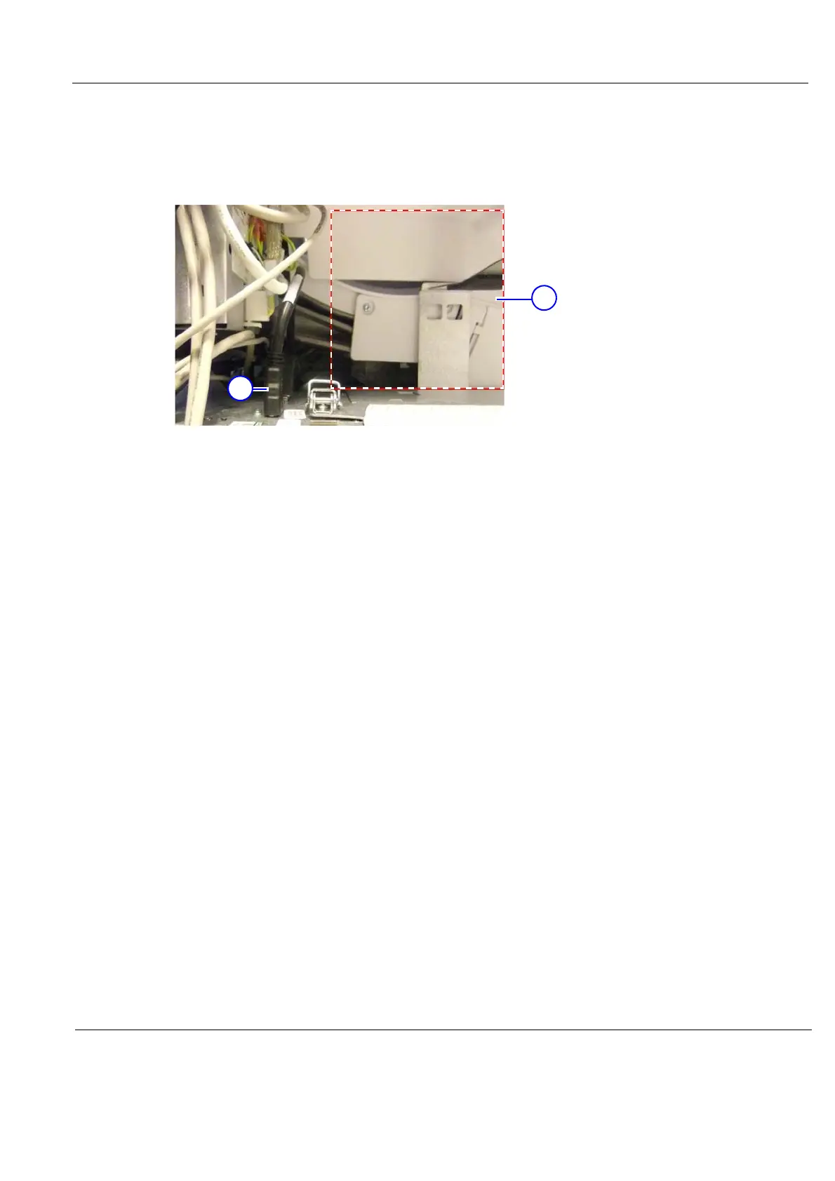
4.) Connect the other end of the GFI PCIe Cable to the connector on top of the BEP.
Ensure that the GFI PCIe Cable is kept out of the drawed box area in Figure 8-208, as there is a
risk that the Z Mechanism damage the cable.
5.) Install the Left Side Cover and the Right side Cover.
Figure 8-208 Keep cables out of the marked area
1. GFI PCIe Cable (at top of BEP)
2. Keep cables out of the marked area