GE
D
IRECTION GB091046, REVISION 2 VIVID E9 / VIVID E7 BT’13 SERVICE MANUAL
2 - 8 Section 2-2 - General console requirements
2-2-3-1 EMI prevention/abatement
2-2-4 Probes environmental requirements
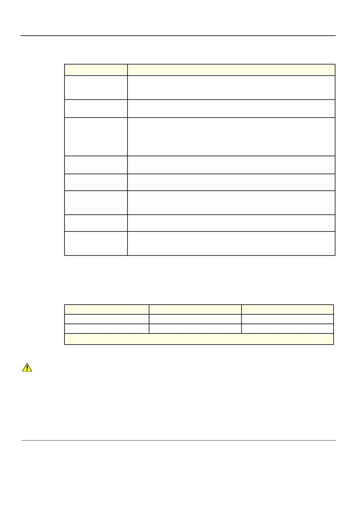
Table 2-3 EMI prevention/abatement
EMI RULE DETAILS
Be aware of RF sources
• Keep the unit at least 5 meters (15 feet) away from other EMI sources.
• Special shielding may be required to eliminate interference problems caused by high
frequency, high powered radio or video broadcast signals.
Ground the Ultrasound
system
• Poor grounding is the most likely reason a unit will have noisy images.
• Check grounding of the power cord and power outlet.
Install all screws, RF
gaskets, covers, cores
• After you finish repairing or updating the system, replace all covers and tighten all screws.
• Any cable with an external connection requires a magnet wrap at each end.
• Install the Card Rack Cover over the Card Rack.
Loose or missing covers or RF gaskets allow radio frequencies to interfere with the ultrasound
signals.
Replace broken RF gaskets
• If more than 20% or a pair of the fingers on an RF gasket are broken, replace the gasket.
• Do not turn on the unit until any loose metallic part is removed.
Do not place labels where
RF gaskets touch metal
Never place a label where RF gaskets meet the unit. otherwise, the gap created will permit RF
leakage. or, if a label has been found in such a position, move the label.
Use GE specified harnesses
and peripherals
• The interconnect cables are grounded and require ferrite beads and other shielding.
• Also, cable length, material, and routing are all important; do not change from what is
specified.
Take care with cellular
phones
Cellular phones may transmit a 5 V/m signal; that could cause image artifacts.
Properly dress peripheral
cables
• Do not allow cables to lie across the top of the Card Rack or hang out of the peripheral bays.
• Loop the excess length for peripheral cables inside the peripheral bays. attach the monitor
cables to the frame.
Table 2-4 Operation and storage temperatures for probes
Electronic PAMPTE
Operation: 10 to 40 ºC (50 to 104 ºF) 5 to 42.7 ºC (41 to 108,9 ºF)
Storage: -20 to 50 ºC (-4 to 122 ºF) -20 to 60 ºC (-4 to 140 ºF)
Temperatures in degrees Celsius (
o
C) conversion to degrees F: (
o
F) = (
o
C * 9/5) + 32
PAMPTE probes are designed for storage temperatures of -20 to +60 degrees C
(-4 to +140 degrees F).
Electronic probes are designed for storage temperatures of -20 to +50 degrees C
(-4 to +122 degrees F).
When exposed to large temperature variations, the product should be kept at room temperature
the needed time to stabilize its temperature before use.
Refer to Table 2-1 "VIVID E9 / VIVID E7 Acclimate Time" on page 2-2 to determine the needed
settlement time.