GE DRAFT VOLUSON™ P8/VOLUSON™P6
DIRECTION 5775469, R
EVISION 3 DRAFT (JULY 19, 2018) BASIC SERVICE MANUAL
Chapter 5 - Components and Functions (Theory) 5-47
5-11-1-3 Power Up Sequence Description
The Power Up Sequence can be divided in the following steps:
• Switch Circuit Breaker in DPS to ON position
• Press the ON button on the Operator Panel
• DRFG power-up
5-11-1-3-1 Power Up Sequence Description
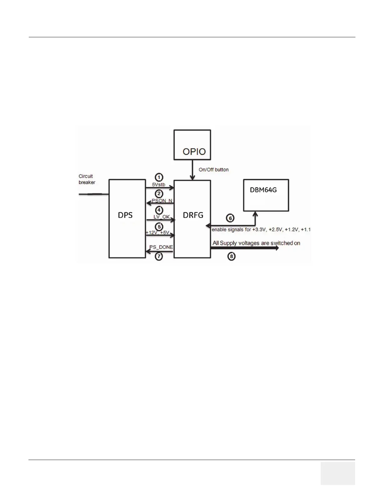
1.) DRFG, powered by 5Vstb, detects contact of Power-On button event.
2.) DRFG sends PSON_N low to DPS
3.) DPS powers up +24V, +12V,
±5V
4.) DPS provides LV_OK as soon as +12V is within specification
5.) DPS provides PC voltages from +12V, +5V.
6.) DRFG distribute enable signals for +3.3V, +2.5V, +1.2V, +1.1 to itself and DBM64G.
7.) DRFG provides PS_DONE output signal to DPS.
8.) All Supply voltages are switched on.
Figure 5-23 Power Up Sequence

 Loading...


