GE DRAFT VOLUSON™ P8/VOLUSON™P6
DIRECTION 5775469, R
EVISION 3 DRAFT (JULY 19, 2018) BASIC SERVICE MANUAL
Chapter 8 - Replacement Procedures 8-135
Section 8-43
Replacement of the SOM in DRFG
8-43-1 Manpower
One person, 30 minutes
8-43-2 Tools
Philips screwdriver
8-43-3 Preparations
1.) Power Off/Shutdown the system as described in 4-3-2 on page 4-4.
2.) Remove the REAR CABINET BEZEL ASSY BT16 and disconnect cables as described in 8-28-4
"Removal Procedure" 2), 3), 4) and 7) on page 8-93.
3.) Remove the NEST EMI BRKT BT16 as described in 8-56-4 "Removal Procedure"
4.) Remove the DRFG as described in 8-42-3 on page 8-130.
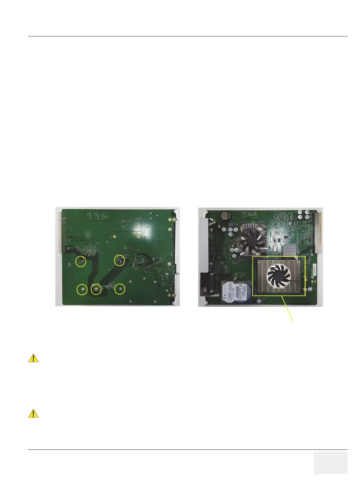
8-43-4 Removal Procedure
1.) Unscrew 5 screws and pull the SOM board out of the DRFG.
8-43-5 Installation Procedure
1.) Install the new parts in the reverse order of removal.
2.) Perform: FRU8-30: Replacement of the SOM in DRFG - Functional Tests.
Figure 8-194 Unscrewing 5 screws and pulling the SOM board out of the DRFG
!! CAUTION:
When replacing with new SOM, Push the SOM in both side of DRFG ASSEMBLY without
putting weight on the board.
As a new specification, the system can be turned off up to 3 times due to recognizing GPU, initializing
Intel device and Bios. In this case, please turn on the system again.
Bottom view
Top view
pull out

 Loading...


