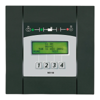
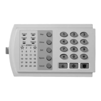
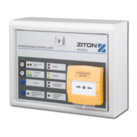
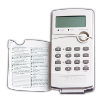
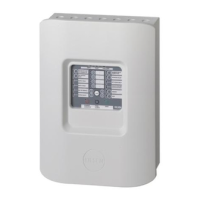
ZP3 Fire Control Panel User Guide
List of illustrations
Figure Page
Figure 1: Typical ZP3 system schematic.........................................................................................................................1
Figure 2: ZP3 Fire control panel ...........................................................................................................................................6
Figure 3: ZP3 Fire control panel fascia panel layout .................................................................................................7
Figure 4: Alarm view buttons and common alarm indicators ..............................................................................7
Figure 5: Zonal fire indicators ...............................................................................................................................................9
Figure 6: Navigation buttons.............................................................................................................................................. 10
Figure 7: Main operating controls.................................................................................................................................... 11
Figure 8: Status indicators................................................................................................................................................... 12
Figure 9: ZP3 Fire panel controls and indicators...................................................................................................... 13
Figure 10: LCD Display - overview................................................................................................................................... 14
Figure 11: Typical zone screen.......................................................................................................................................... 15
Figure 12: Typical point screen......................................................................................................................................... 16
Figure 13: Keypad ................................................................................................................................................................... 21
Figure 14: Main menu............................................................................................................................................................ 22
Figure 15: Operator menu................................................................................................................................................... 22
Figure 16: Menu structure ................................................................................................................................................... 23
List of abbreviations and acronyms
Abbreviation Definition
DC Direct Current
GND Ground
GUI Graphic User Interface
LCD Liquid Crystal Display
LED Light Emitting Diode
mA milliampere
PC Personal Computer
RMC Remote Manned Centre
RX Receive
SW Switch
TX Transmit
V Volts
Associated publications and references
The documents, or parts thereof, that are referenced from this manual are listed below:
Document title Document number
BS5839-1 2002
ZP3 Fire Control Panel Installation, Commissioning and Maintenance manual 503-1160ZE-I-10
ZP3 System maintenance logbook 503-1842ZE-0-02
Revision 11 (05/01/2010) Page v

 Loading...
