13. Operating Instructions
2-75
13-21-2. Hydraulic circuit
1) When mounting any attachment, follow the procedure
below to connect the circuit.
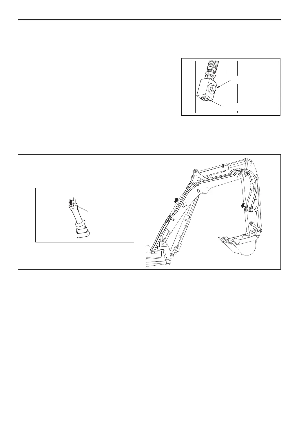
(1) Make sure the stop valves are in the closed position
and remove the screw plugs. Take care not to loose or
damage the removed parts.
(2) Install the connectors supplied by the manufacturer of
the attachment and connect the hoses.
Oil flow system
The directions of lever switch operation and the oil flow
system are described in the figure below.
2) Before disconnecting the hydraulic piping to remove an
attachment, relieve the hydraulic oil pressure in the cir-
cuit according to the following procedure.
(1) Stop the engine.
(2) Turn the starter key to "ON" position.
(3) Push the lock lever forward to set it in unlock position.
(4) Alternatively press the right and left sides of the lever
switch several times.
Screw plug R (PT) 3/4
Stop valve
015576-00E
015577-00E
(For double acting attachment)
Lever switch

 Loading...