10 / 32
1434 µPos
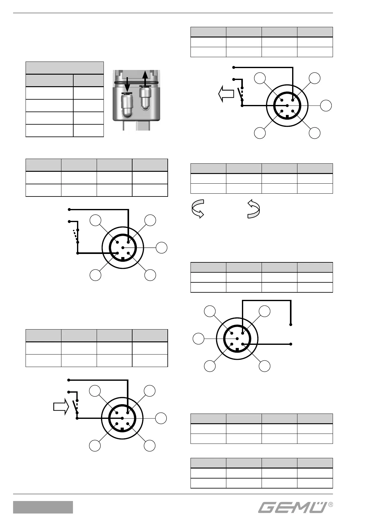
6.1 Elektrischer und
pneumatischer Anschluss
1. Pneumatische Hilfsenergie
(max. 8/10 bar) aktivieren.
Legende
LED Symbol
Aus
m
An
l
Blinkt schnell
b
Blinkt langsam
I
2. Versorgungsspannung 24 V einschalten.
POWER LED leuchtet.
LED Symbol LED Symbol
OPEN
I
CLOSED
I
ERROR
b
POWER
l
6.2 Automatische Initialisierung
1. Initialisierungsspannung 24 V DC an Pin 5
anschließen und aktivieren (t > 100ms).
LED Symbol LED Symbol
OPEN
I
CLOSED
I
ERROR
b
POWER
l
2. Initialisierungsspannung deaktivieren.
LED Symbol LED Symbol
OPEN
I
CLOSED
I
ERROR
m
POWER
l
3. Die automatische Initialisierung wird
durchgeführt.
LED Symbol LED Symbol
OPEN
I
CLOSED
I
ERROR
m
POWER
l
Initialisierung
6.3 Inbetriebnahme
1. Analogen Sollwert 4-20 mA
(0-20 mA/ 0-10 V) vorgeben.
LED Symbol LED Symbol
OPEN
m
CLOSED
m
ERROR
m
POWER
l
2. Nach Beenden der Initialisierung wird
das Prozessventil in die Position gemäß
Sollwertsignal positioniert.
Sollwert min
LED Symbol LED Symbol
OPEN
m
CLOSED
l
ERROR
m
POWER
l
Sollwert max
LED Symbol LED Symbol
OPEN
l
CLOSED
m
ERROR
m
POWER
l

 Loading...
