22 / 32
1434 µPos
C
B
9.
Enclosed for GEMÜ 650 (O-ring C
only for control functions 2 and 3):
7 Pressure disc B
7 O-ring C
10.
D
11.
E
F
3
Enclosed for necessary mounting
kits (O-rings D and F only for
valves with control function NO
and DA. Depending on version,
only one O-ring may be enclosed):
7 O-ring D
7 Adapter E
7 O-ring F
● Move the actuator to the closed position.
● Insert O-ring D and F at the top and
bottom of adapter T.
● Screw adapter E into the actuator
aperture until it stops and tighten.
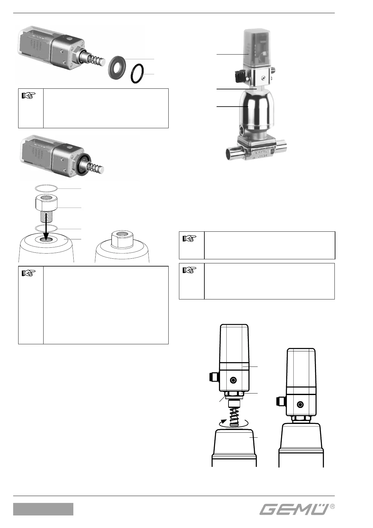
3.2 Mounting the positioner
1
2
3
Valve with positioner
● Assemble the travel sensor (see chapter
3.1 “Assembling the travel sensor”).
l Place the positioner 1 on actuator 3 or
adapter E and fi x it to the travel sensor 2
using a suitable open-end wrench SW 20/
SW 24.
The thread size depends on the
valve to which the positioner is
mounted.
The positioner must not be fi xed
by turning the housing as this may
result in the danger of overturning
the internal stop.
If correctly mounted, the positioner can be
aligned with the corresponding valve.
M16 x 1 - SW 24
M12 x 1 - SW 20
1
2
3
Positioner and
actuator
Positioner mounted to
the actuator
 Loading...

