21 / 32
1434 µPos
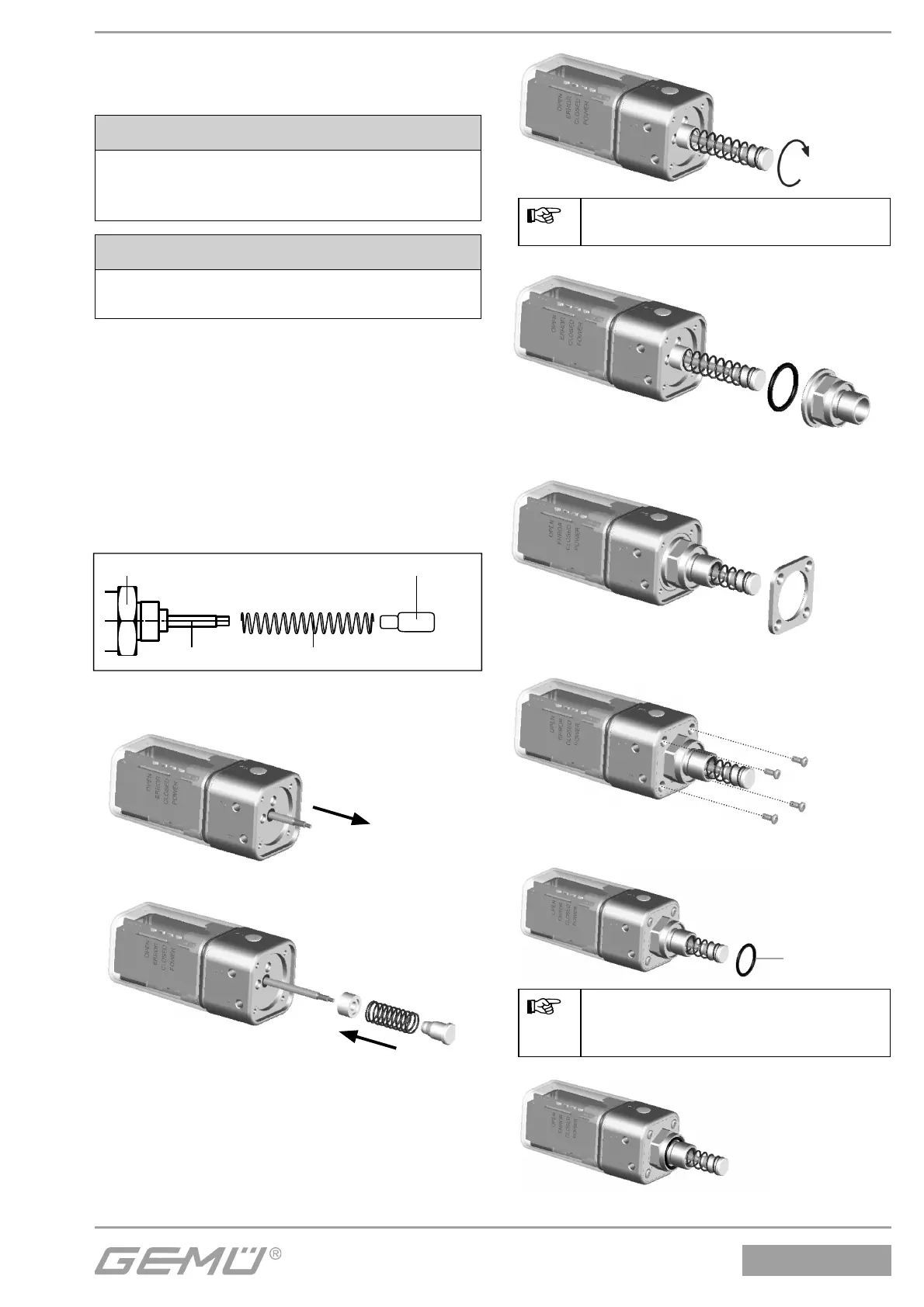
3 Mechanical mounting
3.1 Assembling the travel sensor
CAUTION
Pretensioned spring
ä Damage to the device.
● Slowly release the tension in the spring.
CAUTION
Damage to the spindle surface may
lead to failure of the travel sensor!
The travel sensor is assembled using
a 1434S01Z... (direct mounting) and/
or 4232S01Z... (remote mounting) or
1444000Z... (direct mounting above
mounting bracket) mounting kit, comprising
compression spring, operating bush,
threaded adapter if applicable and/or
mounting bracket. The mounting kit depends
on the valve type.
Travel sensor
Spindle
Compression spring
Operating bush
Mounting kit
1.
2.
3.
Hold the spindle and tighten the
operating bush hand tight.
4.
5.
6.
7.
A
Enclosed for control functions 2
and 3, if no adapter is included:
7 O-ring A
8.
 Loading...

