2 / 40
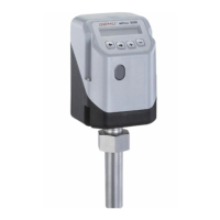
3030
mFlow
Contents
1 General safety information 3
1.1 General information 3
1.2 Explanation of symbols and signs 3
1.3 Safety notes 3
1.4 Correct use 4
1.5 Information on use in damp conditions 4
1.6 Tools required for installation and assembly 4
2 Manufacturer's information 4
2.1 Transport 4
2.2 Delivery and performance 4
2.3 Storage 4
2.4 Function 4
2.5 GEMÜ CONEXO 4
3 Diagrammatic view of the outputs 5
4 Assembly / disassembly 6
4.1 Assembly 6
4.1.1 Assembly with GEMÜ weldolet 7
4.1.2 Assembly with GEMÜ grommet 7
4.1.3 Assembly with GEMÜ wafer-type fl ange 7
4.1.4 Assembly with Tuchenhagen Varivent
®
in-line
housing 7
4.1.5 Assembly with Neumo BioControl
®
in-line housing 7
4.2 Disassembly 8
5 Electrical connections 8
6 Operation 8
6.1 Operating and display elements 8
6.2 Menu levels 8
6.2.1 Working level (Mode) 8
6.2.2 Confi guration level (Setup) 8
7 Changing parameters 8
8 Commissioning 9
9 Operation 9
10 Confi guration menu (Setup) 10
10.1 Changes in the confi guration menu 10
10.2 Access authorisation in the confi guration menu 10
10.3 Menu structure 1 Service 11
10.4 Menu structure 2 SetBasics 12
10.5 Menu structure 3 SetFunction 13
10.6 Menu structure 4 SetCalibration 14
11 Parameter table 15
12 Explanation of parameters 18
12.1 1 Service 18
12.1.1 Scanning the input and output signals 18
12.1.2 Activating or deactivating the user access 18
12.1.3 Reading out, deleting and deactivating
error messages 20
12.1.4 Display serial number, software version and ID,
and enter TAG number 20
12.2 2 SetBasics 21
12.2.1 Reset 21
12.2.2 Select display indication 21
12.2.3 Set the units of measure 21
12.2.4 Set measuring range 21
12.2.5 Making the display settings 21
12.3 3 SetFunction 22
12.3.1 Set the analogue output 22
12.3.2 Setting output functions and
switch points 22
12.3.3 Setting the error time and error action 23
12.3.4 Storing parameter sets 23
12.4 4 SetCalibration 24
12.4.1 Set the fi tting type and nominal size 24
12.4.2 Carry out the calibration 24
13 Error messages 25
14 Table for changes to the factory settings 26
15 Disposal 27
16 Returns 27
17 Information 27
18 Overview of types 28
19 Technical data 29
20 Order data 32
20.1 Order data complete measurement device 32
20.2 Order data separate measurement device 33
20.3 Order data separate fi tting 34
20.4 Order data Connection kit 34
21 Dimensions 35
21.1 Dimensions of fl owmeter 35
21.2 Dimensions of installation fi ttings 36
List of terms 38