7 / 40
3030
mFlow
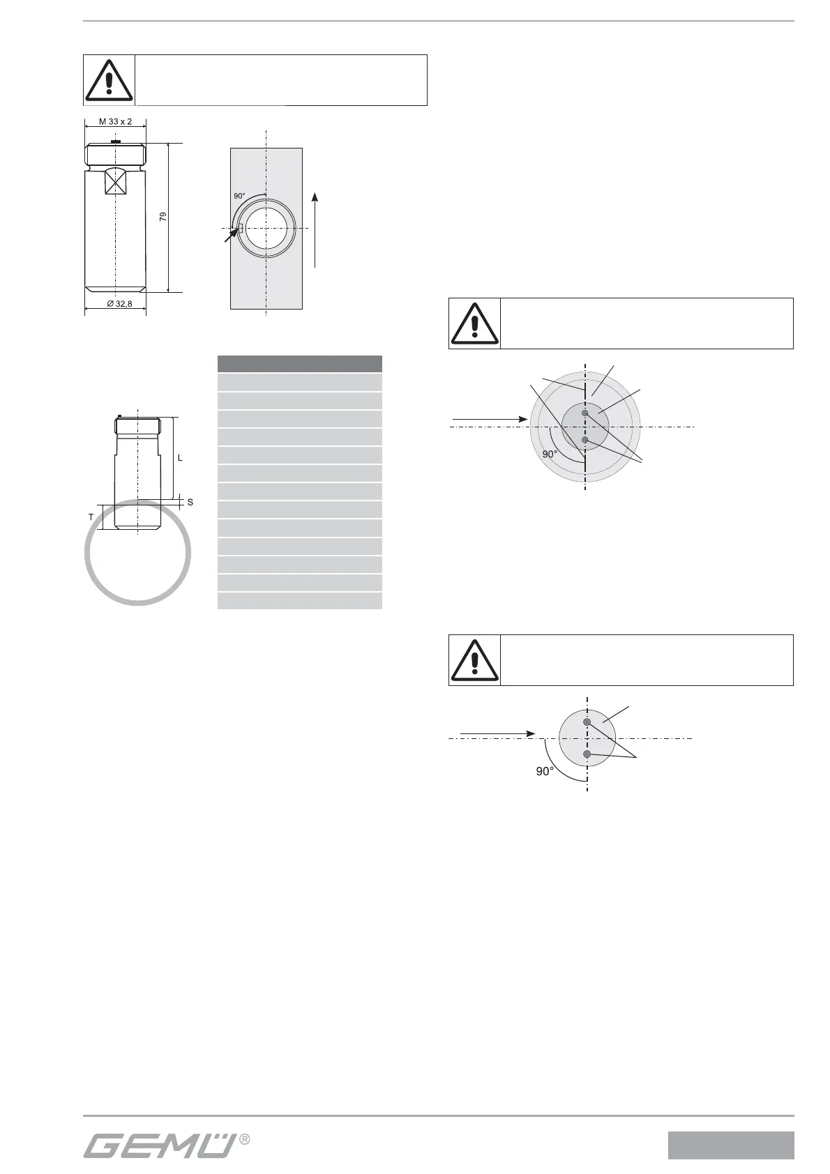
4.1.1 Assembly with GEMÜ weldolet
Do not weld in the weld-in sleeve with the installed
flowmeter.
Flow
Lo-
cking
wing
Figure 1 Figure 2
Figure 3
Table – Installation dimensions
DN T [mm]
25 4.5
32 6.0
40 7.2
50 8.3
65 10.0
80 12.0
100 14.5
125 17.5
150 20.5
200 27.0
250 33.0
300 39.5
The installation depth L is calculated using the following
formula:
L = 79 - S - T
S = Wall thickness of the piping
T = Can be taken from the "Installation dimensions" table for
the respective piping
1. Drill a bolt hole with a diameter 33 in the piping.
2. Insert a weld-in sleeve (fi gure 1) into the bolt hole.
3. Align a locking wing 90° o set to the fl ow direction
(fi gure 2).
4. Weld in a weld-in sleeve with the installation dimension that
is appropriate for the nominal size (fi gure 3, see the "Instal-
lation dimensions" table) vertical to the piping axis.
5. Attach the fl owmeter (ensure that the locking wing is not
twisted).
6. Use the union nut (M33x2, SW36) to attach the fl owmeter
on the weld-in sleeve.
4.1.2 Assembly with GEMÜ grommet
1. Install an in-line housing in the line.
2. Attach the fl owmeter (ensure that the locking wing is not
twisted).
3. Use the union nut (M33x2, SW36) to attach the fl owmeter
on the in-line housing.
4.1.3 Assembly with GEMÜ wafer-type fl ange
1. Install the wafer-type fl ange in the line.
2. Attach the fl owmeter (ensure that the locking wing is not
twisted).
3. Use the union nut (M33x2, SW36) to attach the fl owmeter
on the wafer-type fl ange.
4.1.4 Assembly with Tuchenhagen Varivent
®
in-line
housing
The electrodes of the sensor must always be
assigned precisely at 90° to the flow direction of the
medium to enable a precise measurement.
Closing plate
View of
bottom of
sensor
Flow
Sensor
Electrodes
Markings
1. Weld the Varivent
®
in-line housing into the piping.
2. Position the fl owmeter with welded-on closing plate on the
housing.
3. Ensure that the sensor is aligned correctly (electrodes/
markings 90° o set to fl ow direction).
4. Use the clamp ring to secure the fl owmeter to the housing.
4.1.5 Assembly with Neumo BioControl
®
in-line housing
The electrodes of the sensor must always be
assigned precisely at 90° to the flow direction of the
medium to enable a precise measurement.
View of
bottom of
sensor
Flow
Sensor
Electrodes
1. Weld the BioControl
®
in-line housing into the piping.
2. Position the fl owmeter with welded-on closing plate on the
BioControl
®
in-line housing.
3. Ensure that the sensor is aligned correctly (electrodes 90°
o set to fl ow direction).
4. Screw the fl owmeter on the housing.