48 / 64
613, 618
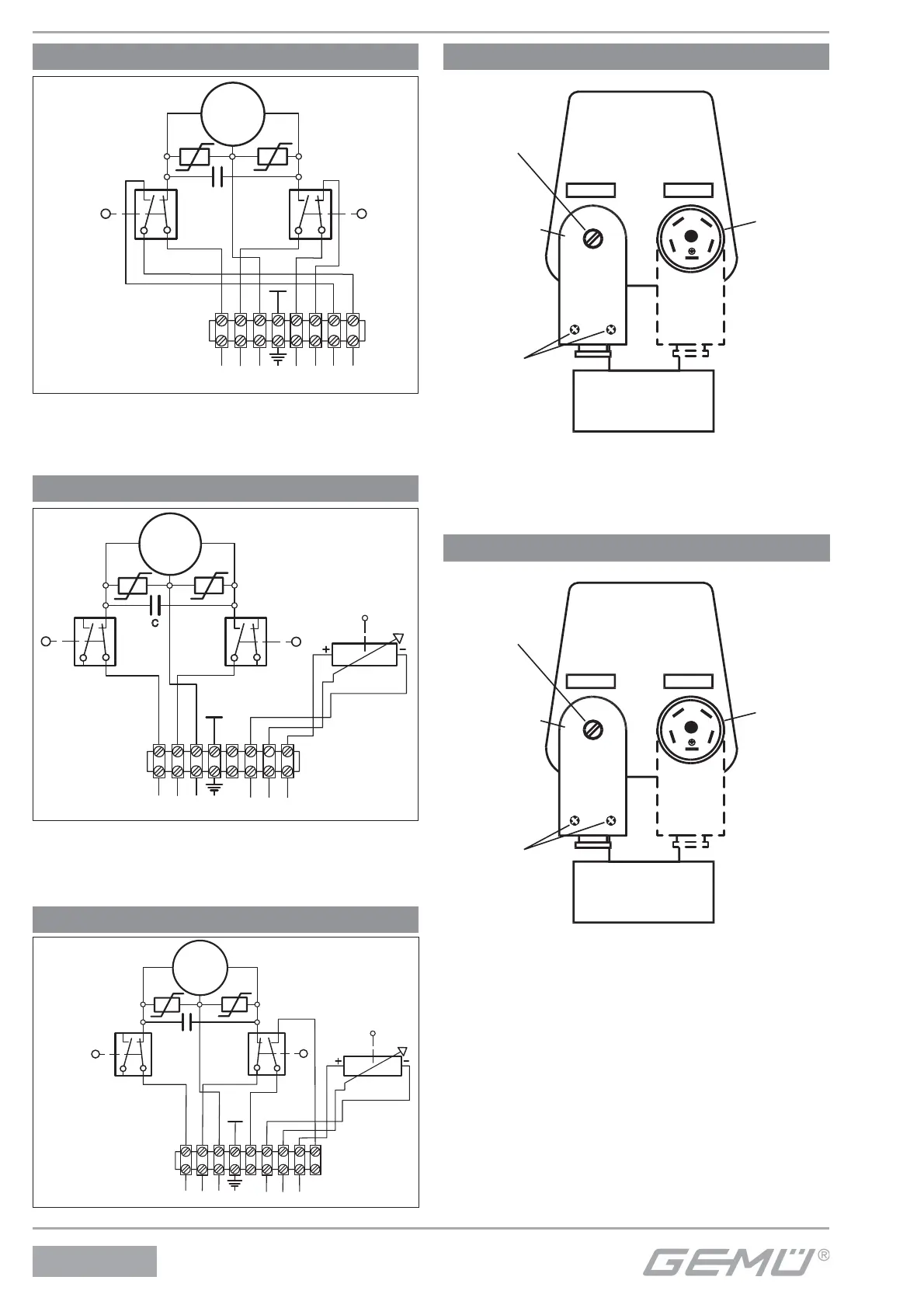
Connection diagram Code AE functional module
8
7
1
2
3
4
5
6
S1 S2
VDR
VDR
W
C
M~
open
closed
N
PE
brown
black
blue
Synchronous
motor
CLOSED
OPEN
The voltage of the end
position feedback must
be identical with the
supply voltage of the
actuator.
Diagram shows CLOSED position - cam has
actuated S2 (limit switch CLOSED) break
contact was opened.
Connection diagram Code AP functional module
Diagram shows CLOSED position - cam has
actuated S2 (limit switch CLOSED) break
contact was opened.
8
1
2
3
4
5
6
S1
VDR
VDR
W
C
M~
7
S2
open
closed
N
PE
brown
black
blue
green
yellow
red
Synchronous
motor
CLOSEDOPEN
linear
Actual value
potentiometer
10 K
8
1
2
3
4
5
6
S1
VDR
VDR
W
M~
7
C
S2
9
Connection diagram K No. 7014
open
closed
N
PE
green
yellow
red
linear
Actual value
potentiometer
10 K
The voltage of the end
position feedback must
be identical with the
supply voltage of the
actuator.
Synchronous
motor
brown
black
blue
CLOSEDOPEN
Connection diagram Code E1 functional module
1
2
3
4
}
Fixing screw
Actuator
Mains
Signal
Connector
plug (mating
connector) with
terminal screws
Mounting
plug in the
actuator
Plug assignment
signal
Ext. set value
Valve body
(diagrammatic view)
Plug assignment
mains
Housing bolts (2)
and (3) of connector
plug
1: N.C.
2: N.C.
3: U-, GND/ 0V to pin 4
4: U+, 0-10V DC signal
5: N.C.
1: L
*1)
2: N
3: N.C.
4: N.C.
5: PE
}
*1) For the supply voltage (mains) check the details on the product
label (24, 120 or 230 V AC).
N.C. = not connected
*1) For the supply voltage (mains) check the details on the product
label (24, 120 or 230 V AC).
N.C. = not connected
Connection diagram Code E2 functional module
1
2
3
4
}
Fixing screw
Actuator
Mains
Signal
Connector
plug (mating
connector) with
terminal screws
Mounting
plug
in the
actuator
Plug assignment
signal
Ext. set value
Valve body
(diagrammatic view)
Plug assignment
mains
Housing bolts (2)
and (3) of connector
plug
1: N.C.
2: N.C.
3: I-, GND/ 0V to pin 4
4: I+, 4-20mA dignal
5: N.C.
1: L
*1)
2: N
3: N.C.
4: N.C.
5: PE
}