49 / 64
613, 618
*1) For the supply voltage (mains) check the details on the product
label (24, 120 or 230 V AC).
N.C. = not connected
Connection diagram Code E3 functional module
Fixing screw
Actuator
Mains
Signal
Connector
plug (mating
connector) with
terminal screws
Mounting
plug
in the
actuator
Plug assignment
signal
Ext. actual value
Valve body
(diagrammatic view)
Plug assignment
mains
Housing bolts (2)
and (3) of connector
plug
1: I-, GND/ 0V to pin 2
2: I+, 4-20mA signal
3: I-, GND/ 0V to pin 4
4: I+, 4-20mA signal
5: N.C.
1: L
*1)
2: N
3: N.C.
4: N.C.
5: PE
}
}
Ext. set value
1
2
3
4
5
6
Functional module AE OPEN / CLOSE
control with 2 additional end position
feedback signals and
Hirschmann plug N 6 R AM2 (design: 6027)
Pin Designation
1 L1, motor voltage for direction of travel OPEN
2 L1, motor voltage for direction of travel CLOSED
3 N, reference voltage
4 L1, S1/S2 (23) limit switch
5 Us, S2 (24) CLOSED end position [Us=Ub]
6 Us, S1 (24) OPEN end position [Us=Ub]
7
, PE
1
2
3
4
5
6
Pin Designation
1 L1, motor voltage for direction of travel OPEN
2 L1, motor voltage for direction of travel CLOSED
3 N, reference voltage
4 Us +, actual value potentiometer, signal voltage
5 Us -, actual value potentiometer, signal output
6 Us
, actual value potentiometer, signal voltage
7
, PE
Functional module AP OPEN / CLOSE
control with potentiometer output and
Hirschmann plug N 6 R AM2 (design: 6027)
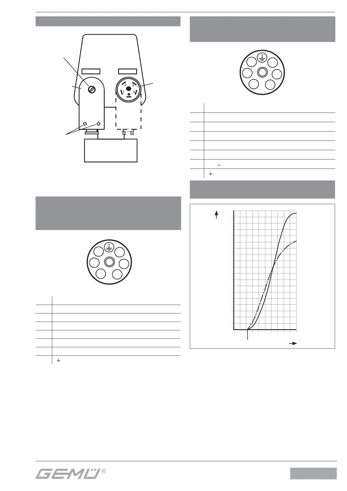
Characteristic progress with functional
module E2 or 3-point controller 1283
3,8
3,6
3,4
3,2
3,0
2,8
2,6
2,4
2,2
2,0
1,8
1,6
1,4
1,2
1,0
0,8
0,6
0,4
0,2
0
0 2 4 6 8 10 12 14 16 18 20
I [mA]
Q [m³/h]
DN 15
DN 12
Opening point
Medium:
Water
p: 1 bar