Pag.15
5.3.4
Connection
Danger!
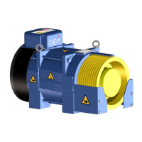
The motor cable must be connected to the correct phase of the frequency inverter and the elevator
machine: U -> U / V -> V / W -> W (or L1 -> U / L2 -> V / L3 -> W or R -> U / S -> V / T -> W).
If the actual direction of travel does not correspond to the selected direction, the turning direction of the
elevator machine must be changed in the frequency inverter configuration. If the motor cable is not
connected to the correct phase, control of the elevator machine is not possible. It can result in jerky
movements or uncontrolled acceleration of the elevator machine.
5.3.5
Connection requirements
Connection Standard
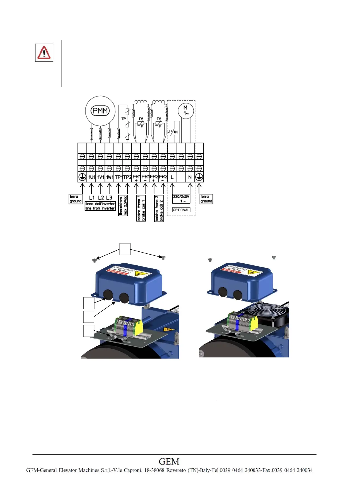
Connection with forced ventilation
Standard connection requirements
1.
Loosen both recessed cheese head screws M6 (1)
2.
The cover plate (2) can now be removed
3.
Connect the GLSxx according to the connection diagram (attached under the cover plate)
4.
Cables must be passed through the rubber rings (3) and clamped with the cable clamps (4)
5.
Ground and shield of motor cable must be plugged in the yellow/green terminal
6.
U,V,W sequence must be respected
7.
Connect PTC (see below)
8.
Connect brake and brake micro’s
9.
Remount the cover plate (2)
10.
Tighten the M6 screws (1)
1
2
3
4