Pag.19
5.5.1
Application
•
The brakes are intended for static applications as holding brakes. Dynamic braking must be
restricted to emergency and inspection braking. No wear occurs on a holding brake. This means
that the brake is maintenance free, and only the air gap has to be checked as described in the
“Maintenance and repair - Inspection intervals - Checking the air gap” chapter.
5.5.2
Mechanical releasing
Mechanical release of the brakes is possible by using the manual hand release system available as an
option. Two different types of levers are available for manual hand release of the brake: long levers
for local manual hand release; short levers for remote hand release by mean of a Bowden cable and
a remote lever.
Both type are easily retrofittable on existing brakes.
5.5.3
Release monitoring
•
The brake release monitoring serves as monitoring for redundancy and the operation status of the
brakes.
•
Release monitoring for the brakes is carried out by a couple of microswitches. For
technical data,
see chapter "Appendix - Technical data - Microswitch".
5.5.4
Brake control
5.5.4.1
Electromechanical contactors
To reduce noises during brake disconnection the brakes should be switched to the alternating current
side (K4), while normal operation. The brakes are switched-off slower and thus quieter through the
rectifier.
To ensure instantaneous brake engagement in emergencies, during inspection runs and return
runs, a second contactor (K3), which disconnects the brake on the direct current side, should be
used. This
contactor is to be switched depending on the safety circuit.
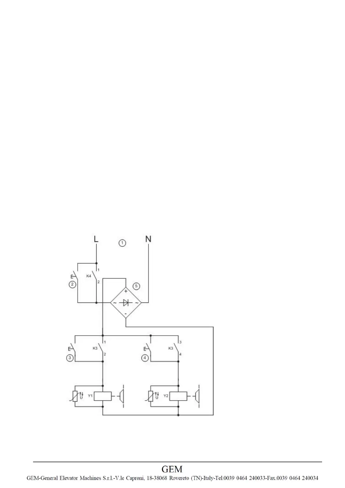
Simplified diagram for brake control
1
Voltage supply
2
Button circuit test
3
/ 4 “Open brake” button
5 Rectifier
K3 Brake contactor, activated by safety circuit
K4 Brake contactor, activated by control or frequency inverter
 Loading...