Pag.21
5.6
Forced cooling
GLSxx forced ventilation (optional): the forced ventilation is optional and can be added
afterwards.
Forced ventilation is suggested only in case of intense lift traffic (offices, hospitals,…), high lift room
temperatures, high cabin travel (>50m).
5.6.1
Technical data
Voltage 220 - 240 [V]
Frequency 50 / 60 [Hz]
Power 20 / 19 [W]
Current 0.13 / 0.11 [A]
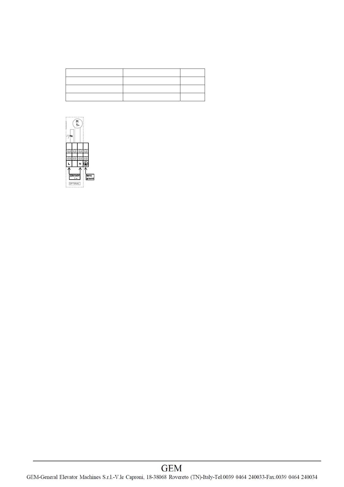
5.6.2
Connection diagram
TM Thermal contact N.O. 70
°
C
6
Start-up
6.1
Operating conditions
The elevator machine must be installed in a not free accessible machine room or a closed hoist-
way.
Be aware of the protection class specified on the name plate.
Do not operate the elevator machine in an explosive atmosphere.
6.2
First Start-up
Before first-time start-up, check the following:
Installation and electrical connection have been properly completed.
Safety devices are installed.
All leftover installation materials and other foreign materials have been removed.
The protective ground is connected.
Motor protection correctly connected and operative.
Cable entries closed.
Mounting, installation position and accessories are o.k.
Connection data corresponds to the data on the name plate.
6.3
Tests
Tests on elevator systems can be performed by the assembly company or a certification authority or
organisation. This involves discovering of failure-critical and hazardous conditions. The relevant
operator
is responsible for safety. The descriptions below are intended as recommendations for the
technical
procedure and do not deal in sufficient depth with safety engineering aspects of the relevant
system.
Therefore, priority is given to the safety engineering specifications of the assembly company
or operator.
Only trained specialist personnel may carry out tests.
6.3.1
Run the machine without load
Before installing the ropes on the traction sheave check that the motor run freely in both sense of
rotation with a current absorbtion of less than 0,5A. In case a greater value of current is measured
verify that the inverter input parameters are correct and that the brake opens correctly.
6.3.2
Half load test with current measurement.
The test for the 50 % weight compensation should preferably be carried out as follows:
The motor current is to be measured in both travel directions with a half load.