Pag.16
Connection requirements with optional forced ventilation
1.
Loosen both recessed cheese head screws M6 (1)
2.
The cover plate (2) can now be removed
3.
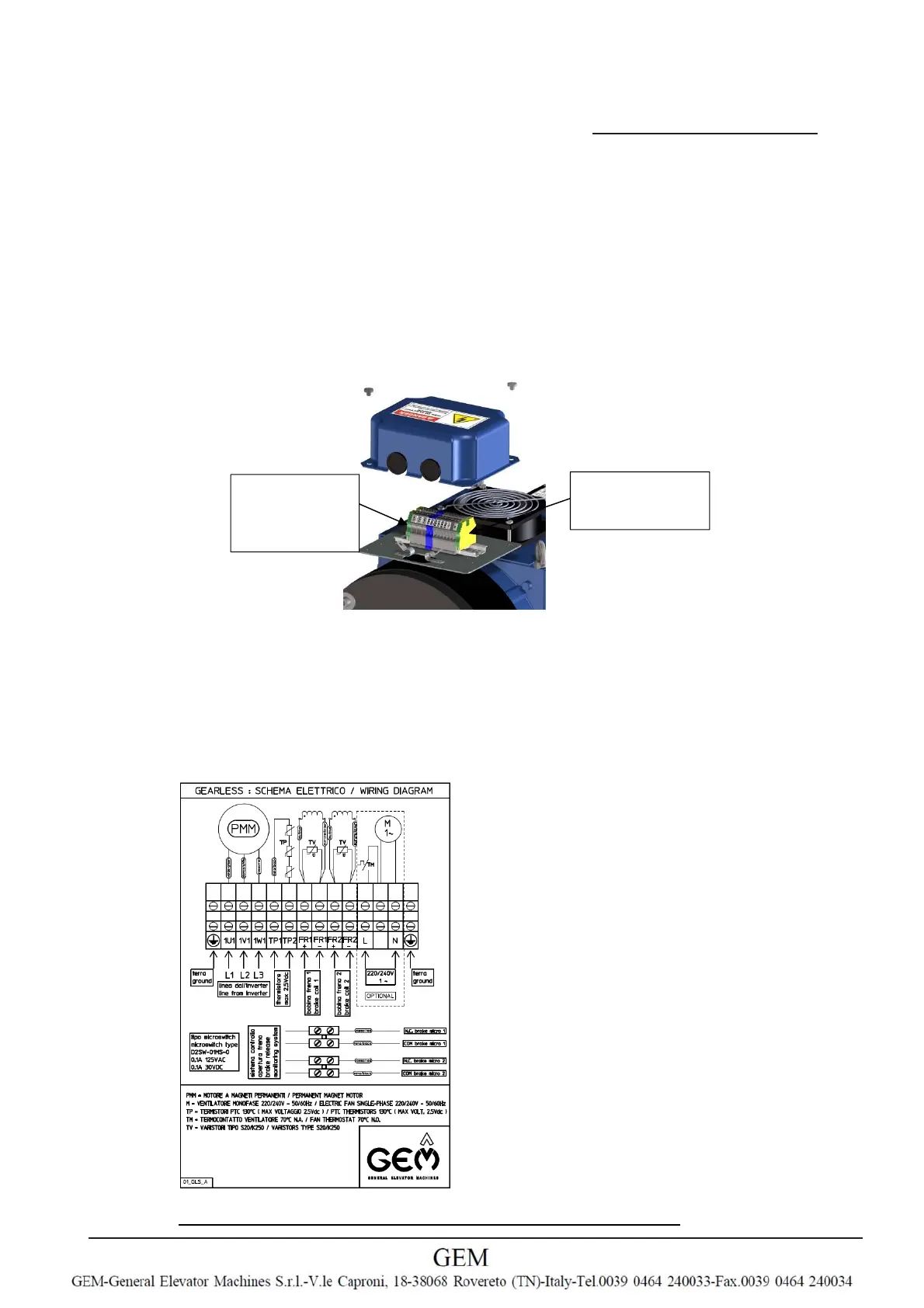
Connect the GLSxx according to the connection diagram (attached under the cover plate)
4.
Cables must be passed through the rubber rings (3) and clamped with the cable clamps (4)
5.
Ground and shield of motor cable must be plugged in the yellow/green terminal
6.
U,V,W sequence must be respected
7.
Connect PTC (see below)
8.
Connect brake and brake micro’s
9.
Connect the fan supply line (220÷240V monophase 50/60Hz) to the L and N terminals
10.
Remount the cover plate (2)
11.
Tighten the M6 screws (1)
5.3.6
Protective ground connection
Two terminals are dedicated to ground protective connection: one is for the motor ground cable and
for the motor cable shield and the other one is for services. A good ground connection is mandatory!
Protective ground connection
5.3.7
Temperature monitoring
•
The PTC thermistor motor protection must be connected.
•
Only connect to monitor inputs approved for PTC thermistors.
•
Maximum permissible test voltage for PTC thermistors 2.5 V DC.
5.3.8
Connection diagram
The electrical connection diagram is attached under the cover plate.
Motorground
andshield
terminal
Servicesground
terminal