Cinterion
®
Java Terminals Hardware Interface Description
3.8 Power Supply
35
EHSxT_BGS5T_HID_v02 2014-05-23
Confidential / Preliminary
Page 29 of 70
3.8 Power Supply
The power supply of the Java Terminals has to be a single voltage source of V
PLUS
=8V…30V
capable of providing a peak current (pulsed 2x577ms at T=4.615ms) of about 1.2A at 8V during
an active transmission. The uplink burst causes strong ripple (drop) on the power lines. The
drop voltage should not exceed 1V, but the absolute minimum voltage during drops must be
>7.6V.
The Java Terminals are protected from supply voltage reversal. An external fast acting fuse
>
0.4A with melting integral I
2
t (0.15 … 0.25)A
2
s is necessary to use the Java Terminals at a
12V or 24V unlimited power supply system.
The power supply must be compliant with the EN60950 guidelines. A switching regulator reg-
ulates the input voltage for the internal supply.
When power fails for >1ms, Java Terminals reset or switch off. The watchdog can be configured
to restart the Java Terminals. When power fails for >15s the RTC will be reset.
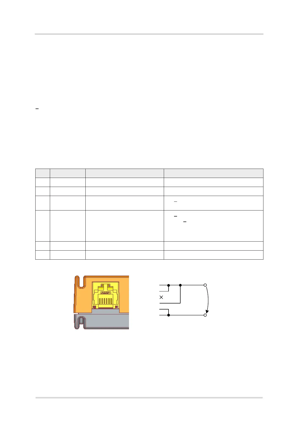
Figure 9: 6-pole Western jack for power supply, ignition, reset, typical connection
Mains adapter: If it fits into the design of your application we recommend the plug-in supply unit
used with the type approved Gemalto M2M reference setup. Ordering information can be found
in Chapter 7. This 12V mains adapter comes with a 6-pole Western plug and provides an inter-
nal connection between IGT_IN pin and PLUS pin for auto ignition (power up).
Table 13: Female 6-pole Western plug for power supply, ignition, power down
Pin Signal name Use Parameters
1 PLUS Power supply 8V – 30V DC, max. 33V for 1 min
2 PLUS Power supply 8V – 30V DC, max. 33V for 1 min
3 RST_IN Signal for module reset U
IH
> 8V for t>10ms resets the terminal.
U
IL
<2V and low level for normal operation.
4 IGT_IN Ignition U
IH
>8V
Ignition >
8V for more than 200ms switches
the Java Terminals on. Ignition is activated
only by a rising edge. The rise time is
<20ms
5 GND Ground 0V
6 GND Ground 0V
Pin assignmment and typical connection:
1 PLUS
2 PLUS
3 RST_IN
4 IGT_IN
5 GND
6 GND
V
PLUS
DC
6 5 4 3 2 1
11
 Loading...