Cinterion
®
Java Terminals Hardware Interface Description
8.4 Configuration via I
2
C Interface
69
EHSxT_BGS5T_HID_v02 2014-05-23
Confidential / Preliminary
Page 65 of 70
8.4 Configuration via I
2
C Interface
While the complete watchdog functionality may be configured via ASC0 interface (for details
see Section 8.3) some of the configuration commands can also be configured during runtime
via I
2
C interface as described in this section.
The I
2
C interface is accessible either via the external Weidmueller connector - I2CDAT and
I2CCLK, or via the Java module‘s AT command interface (e.g., ASC0), or through a Java MID-
let during runtime.
The I
2
C interface implements the write and the read protocol as described in Section 8.4.1. The
7-bit device address is 0x6A (binary: 1101010). The default address can be changed by con-
figuration command (see Section 8.3.1.9).
8.4.1 Command Specification
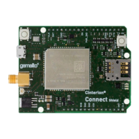
8.4.1.1 WRITE Command Syntax
Example setting the GPIO12 signal direction to “output” (see also section Examples):
Legend:
S: Start Condition, W: Write bit (=0), A: Acknowledge, P: Stop Condition.
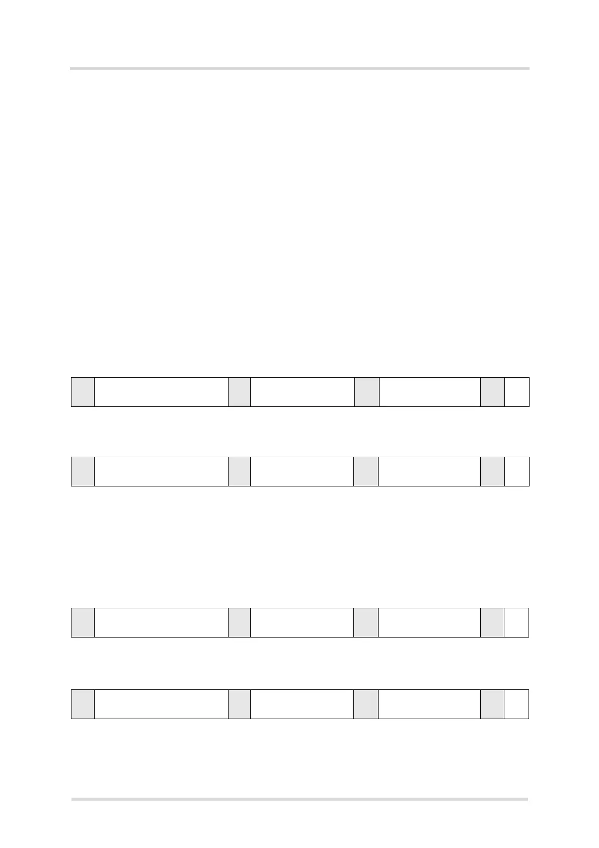
8.4.1.2 READ Command Syntax
Example reading the last status = OK (see also section Examples):
Legend:
S: Start Condition, R: Read bit (=1), A: Acknowledge, N: Not Acknowledge, P: Stop Condition.
S Slave address
(including write bit “W“)
A Register address A Data byte AP
S0xD4
(including write bit “0“)
A 0x14 A 0x01 AP
S Slave address
(including read bit “R“)
A Register address A Data length
(only one byte)
NP
S 0xD5
(including read bit “1“)
A 0x00 A 0x01
(only one byte)
NP
 Loading...