PAGE 26
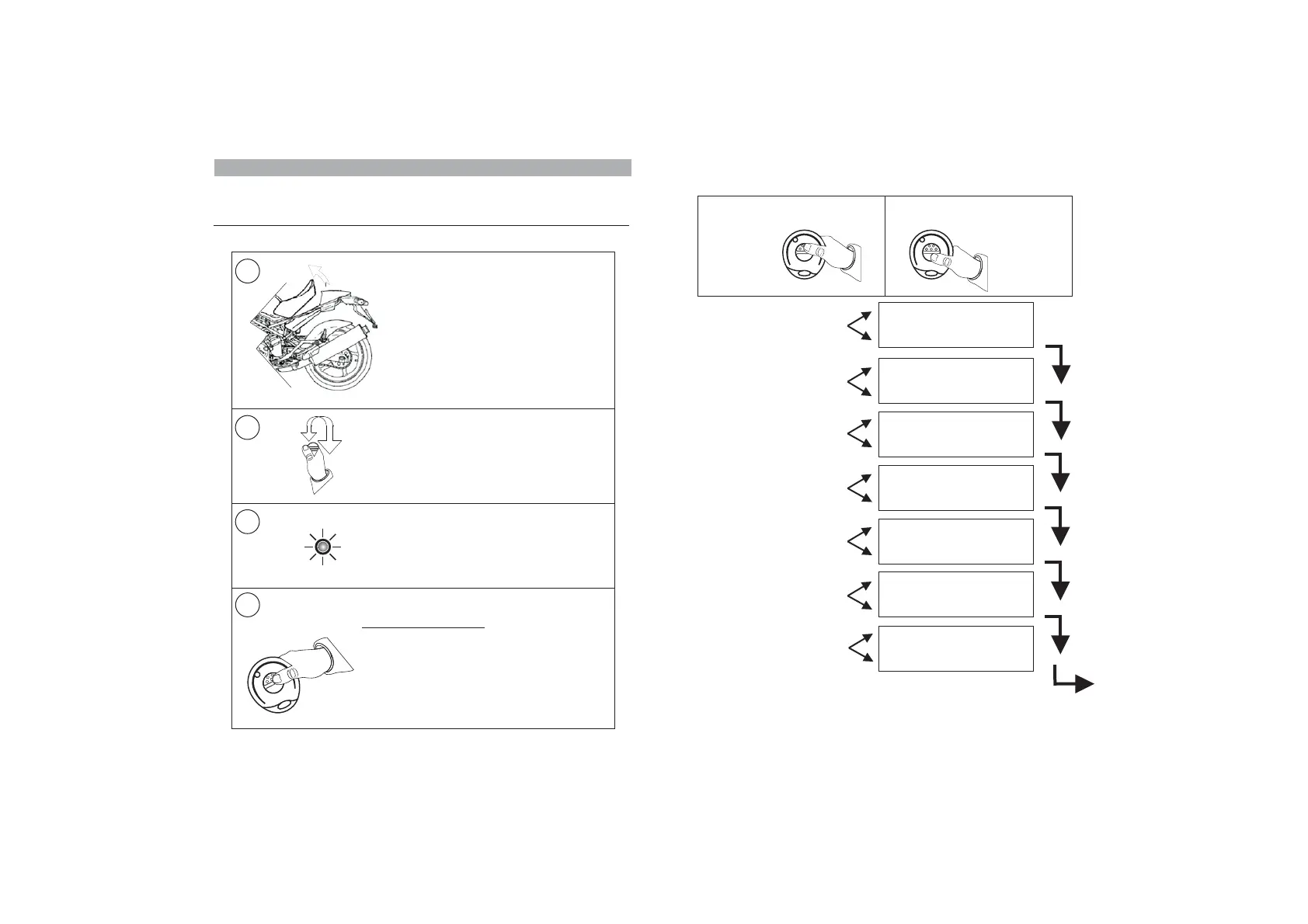
After pressing both buttons simultaneously (step 4), program the features
according to your needs.
EXIT PROGRAMMING
24.0 - PROGRAMMABLE FEATURES
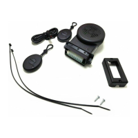
To either enable or disable one of the programmable features, proceed as
follows:
NB: Remember to ALWAYS arm/disarm the system before programming.
4
2
3
With the system disarmed, lift the seat
or open the topcase (if protected by a
contact switch) otherwise ground the
GREEN/BROWN wire.
NB: Remove the wire from ground after
programming.
Turn ignition key in ON.
The status LED will light up for approx. 1 sec.
While the LED is ON, simultaneously press
both remote control buttons.
Two confirmation tones (1 Bop and 1 Beep)
will acknowledge the system is in
programming mode.
The LED will light up steady.
1
Button ENABLE
Button DISABLE
1:
2:
Button 1: ENABLE
2: DISABLEButton
Button ENABLE
Button DISABLE
1:
2:
Button ENABLE
Button DISABLE
1:
2:
Button ENABLE
Button DISABLE
1:
2:
Button ENABLE
Button DISABLE
1:
2:
Button ENABLE
Button DISABLE
1:
2:
PANIC
()
ALARM
factory enabled
ACOUSTIC SIGNALS
(factory enabled)
TILT SENSOR
(factory enabled)
SYSTEM SELF-REARMING
()factory disabled
PASSIVE ARMING
()factory disabled
ANTI-HIJACK
()factory disabled
PRE-ALARM
()factory disabled
TO ENABLE
TO DISABLE
Press button 1
Press button 2
PAGE 25