AC GENERATORS
PART 2
Page 49
Required Tools
•A Volt-Ohm-Meter (VOM) equipped with a MIN/MAX feature
•Meter test leads that are capable of measuring voltage inside
a connector without damaging the socket. A set of black
and red test leads for this application are available from
the manufacturer. Contact your nearest servicing dealer for
more information.
Note: It is not recommended to use any testing device other
than the manufactures approved test lead adapters (P/N
0J09460SRV).
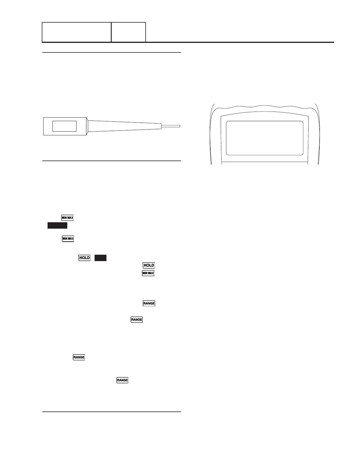
Figure 47. Narrow Test Probe
VOM Setup
Below is an excerpt taken from a Fluke 117 multi-meter owners
manual.
MIN/MAX – The MIN MAX AVG recording mode captures the
minimum and maximum input values (ignoring overloads), and
calculates a running average of all readings. When a new high
or low is detected, the Meter beeps.
•Put the Meter in the desired measurement function and range.
•Press to enter MIN MAX AVG mode.
• MIN MAX and MAX are displayed and the highest reading
detected since entering MIN MAX AVG is displayed.
•Press
to step through the low (MIN), average (AVG),
and present readings.
•To pause MIN MAX AVG recording without erasing stored
values, press
. HOLD is displayed.
•To resume MIN MAX AVG recording, press
again.
•To exit and erase stored readings, press for at least
one second or turn the rotary switch.
RANGE – When you turn the Meter on, it defaults to Autorange
and Auto is displayed.
1. To enter the Manual Range mode, press . Manual is
displayed.
2. In the Manual Range mode, press to increment the
range. After the highest range, the Meter wraps to the
lowest range.
Note: You cannot manually change the range in the MIN
MAX AVG or Display HOLD modes.
If you press
while in MIN MAX AVG or Display Hold,
the Meter beeps twice, indicating an invalid operation, and the
range does not change.
3. To exit Manual Range, press for at least 1 second or
turn the rotary switch. The Meter returns to Autorange and
Auto is displayed.
Procedure: Fixed Excitation Test
1. Remove the 7.5 amp fuse from the controller.
2. Locate and disconnect the J5 connector from the
controller.
3. Set VOM to measure AC voltage.
4. Using the scale feature of the VOM, set to the first available
scale greater than 100 (i.e. “600”).
Note: Refer to the manufactures owners manual for spe-
cific information on using manual scaling
0.00 VAC
MIN/MAX MAX
600
Figure 48.
5. Set meter to MIN/MAX.
Note: Refer to the manufactures owners manual for
specific information on using the MIN/MAX feature.
6. Using the approved meter test probes, connect one meter
test lead to Pin 14-J5 (Wire 6) and the other meter test
lead to Pin 5-J5 (Wire 2).
7. Re-install the 7.5 amp fuse.
8. Set the AUTO-OFF-MANUAL switch to the MANUAL
position.
9. Measure and record the voltage indicated between Wires
2 and 6 as indicated by the VOM.
10. Acknowledge and reset the “under-voltage” present on the
controller; leave AUTO-OFF-MANUAL switch in the OFF
position.
11. Re-locate meter test probes to Pin 11-J5 (Wire 11) and
Pin 10-J5 (Wire 44).
12. Set the AUTO-OFF-MANUAL switch to the MANUAL
position.
13. Measure and record the voltage indicated between Wire
11 and 44 as indicated by the VOM.
14. Acknowledge and reset the “under-voltage” present on the
controller; leave AUTO-OFF-MANUAL switch in the OFF
position.
Section 2.4
Diagnostic Tests
 Loading...


