Unpacking and Inspection
Installation Guidelines for 60 Hz EcoGen™ Generator 9
10. Perform a visual inspection for any hidden freight
damage. If damage is present, contact the freight
carrier.
Figure 2-5. Inspect for Damage
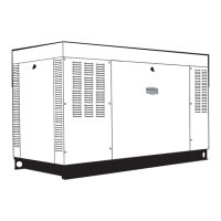
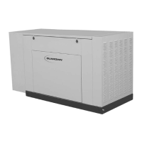
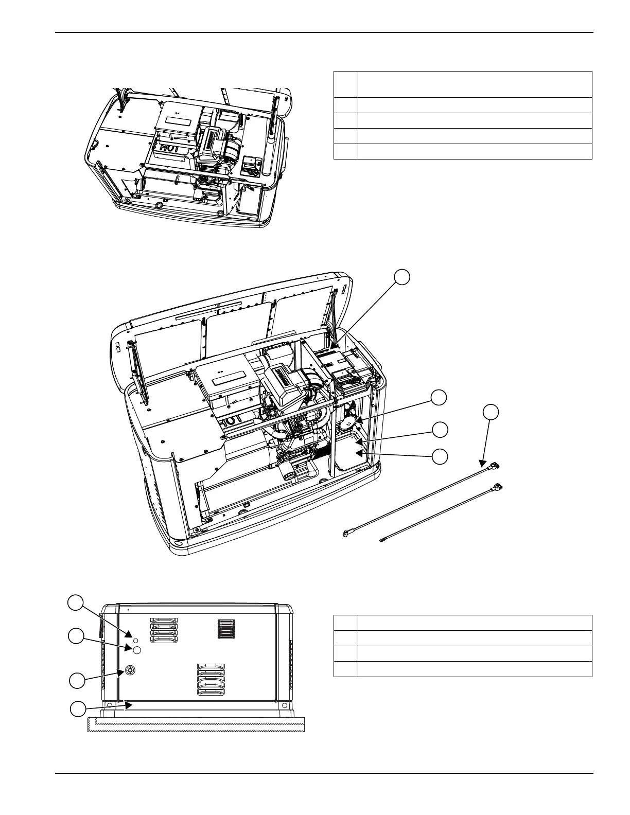
11. Figure 2-6 illustrates the following:
Figure 2-6. Customer Connection Area and Loose Parts Location
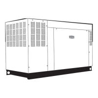
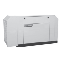
Figure 2-7. Rear of Generator
Figure 2-7 illustrates the following:
A. Customer connection area (underneath and behind
the control panel)
B. Fuel regulator
C. Battery compartment
D. Positive (+) and Negative (–) Battery Cables
E. Location of “Parts Shipped Loose”
A. Main AC/Control Wiring hole for 3/4 inch conduit
B. Main AC/Control Wiring hole for 1–1/4 inch conduit
C. Fuel Inlet Connection
D. Base Fascia (if equipped)
 Loading...