Electrical System
Installation Guidelines for Protector Diesel Generators 19
Section 5: Electrical System
General Information
All wiring must be correctly sized, routed, supported, and
connected. All wiring must comply with NEC and local
codes.
The generator uses Customer Connection Interface
(CCI) panels to separate high voltage and customer con-
trol wiring connections. These two panels are clearly
labeled. The wiring diagrams for each specific unit show
the connection points in their corresponding sections.
Terminal boards are clearly labeled and correspond to
the same terminal connections shown in the wiring dia-
grams. Always use unit specific wiring diagrams when
making wiring connections.
NOTE: See Alternator AC Lead Connections.
Connecting Generator Feeder
Conductors
Installation and interconnection diagrams are provided at
the back of this manual.
NOTE: All installations must comply with national, state,
and local codes. It is the responsibility of the installer to
perform an installation that will pass the final electrical
inspection.
The generator supply connection is made at the genera-
tor disconnect circuit breaker terminals. Conductor sizes
must be adequate to handle the maximum current to
which they will be subjected, based on the 75 °C column
of tables, charts, etc. used to size conductors. The instal-
lation must fully comply with all applicable codes, stan-
dards, and regulations.
All power cables can enter the enclosure through the
knockouts provided.
NOTE: Apply corrosion inhibitor to conductors if alumi-
num conductors are used.
Tighten terminal lugs to the torque values as noted on the
decal located on the inside of the door. After tightening
terminal lugs, carefully wipe away any excess corrosion
inhibitor.
Connect generator conductors to clearly marked terminal
lugs in generator as follows:
1. Connect generator conductors to disconnect circuit
breaker.
2. Connect generator neutral to neutral terminal bar.
3. Connect equipment ground to equipment ground
lug.
Connecting Start Circuit Wires
Control system interconnections may consist of N1, N2,
and T1, and leads 23 and 194. The generator control wir-
ing is a Class 1 signaling circuit. See instruction manual
of specific engine generator for wiring connection details.
Recommended wire gauge sizes for this wiring depends
on the wire length, as recommended in the following
chart:
Exception: Conductors of AC and DC circuits, rated
1,000 volts nominal, or less, shall be permitted to occupy
the same equipment, cable, or conduit. All conductors
shall have an insulation rating equal to at least the maxi-
mum circuit voltage applied to any conductor within the
equipment, cable, or conduit. See NEC 300.3(C)(1).
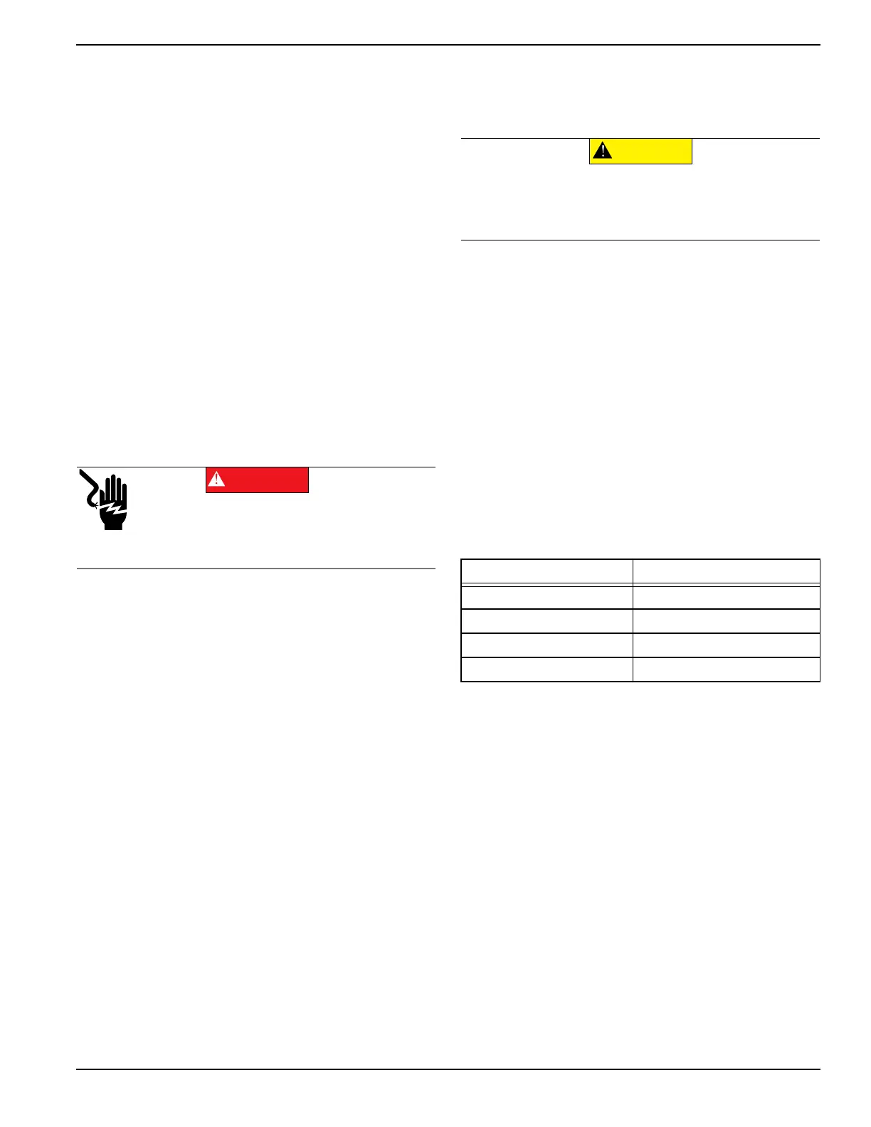
Electrocution. Turn utility and emergency
power supplies to OFF before connecting
power source and load lines. Failure to do so
will result in death or serious injury.
(000116)
DANGER
Maximum Wire Length Recommended Wire Size
1–115 ft (0.3–35 m) No. 18 AWG
116–185 ft (36–56 m) No. 16 AWG
186–295 ft (57–89 m) No. 14 AWG
296–460 ft (90–140 m) No. 12 AWG
(000120)
CAUTION
Equipment damage. Verify all conductors are tightened
to the factory specified torque value. Failure to do so
could result in damage to the switch base.
 Loading...