Electrical System
20 Installation Guidelines for Protector Diesel Generators
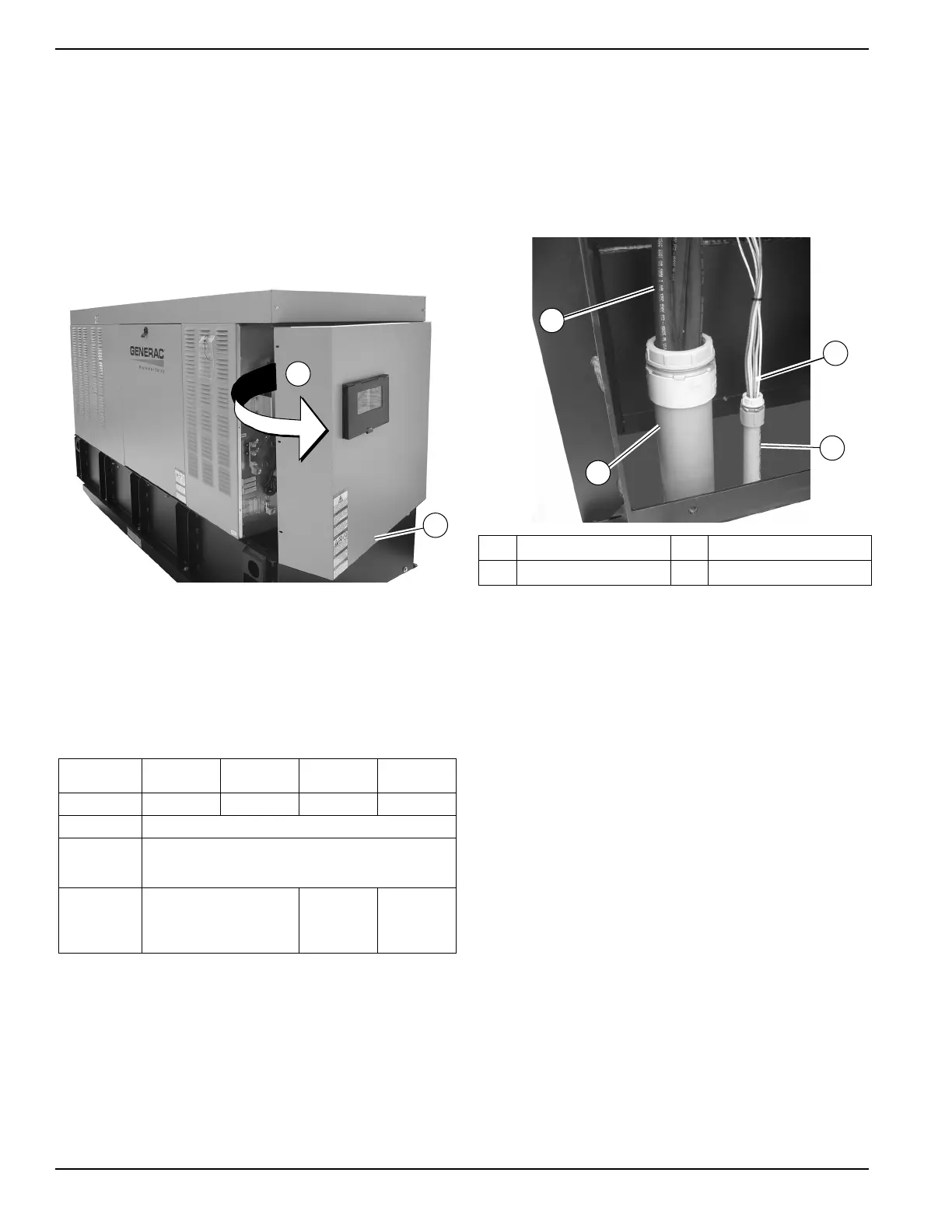
Remove Rear Panel and Stub-Up
Cover
1. See Figure 5-1. Remove six screws with nylon
washers to release rear panel (A) from enclosure.
For best results, rotate left side of panel outward
away from enclosure before disengaging right side.
NOTE: Disconnect wire harness from switch located in
the customer access assembly housing. This will allow
door to be completely removed.
Figure 5-1. Remove Rear Panel and Stub-Up Cover
2. Remove four screws with nylon washers to release
fascia from control panel.
3. The stub-up cover (B) and five screws with flat
washers are shipped loose and found inside the
enclosure.
NOTE: Lug torque specifications are located on breaker
data tag.
Typical Load Leads and Control
Wiring in Stub-Up
NOTE: The illustration in Figure 5-3 is for reference only.
See installation drawings for unit-specific details.
NOTE: See 300.3(C) and Article 725 in the NEC for rout-
ing of Class 1 control wires and power wires. The instal-
lation of a single conduit is permitted.
Figure 5-2. Load Leads and Control Wiring in Stub-
Up (Typical)
Customer Load Wiring
Customer load wiring consists of single-phase or three-
phase connections between generator main line circuit
breaker (MLCB) and transfer switch. The wiring connects
to lugs E1, E2, E3 (if three-phase on MLCB), neutral, and
equipment ground at generator and runs to correspond-
ing lugs in transfer switch. All load wires, neutral, and
ground should be marked and terminated in correct lugs
in transfer switch. Verify all wiring is correctly mounted
and terminated at the appropriate connection points in
both the generator and transfer switch. For general infor-
mation regarding wire type, temperature rating, size
range, and wire lug torque specifications, see Table 5-1.
Always see NEC tables for specific requirements.
NOTE: For three-phase applications, use phase rotation
meter to verify generator phase rotation matches rotation
of utility.
NOTE: For three-phase, delta configured alternators
(voltage code J) the second leg (N2) must be bonded to
all second legs in the entire system.
See Installation Drawings for more information.
Table 5-1. Frame Breakers
Frame
Breaker
Generac 225
AF 2 Pole
Generac 225
AF 3 Pole
Generac 400
AF 2 Pole
Generac 400
AF 3 Pole
Range
125A-200A 50A-200A 225A-400A 225A-400A
Wire Type
Cu/Al
Wire
Temperature
Rating
167 °F
(75 °C)
Lug AWG
Range
(Number of
Conductors)
6-350 kcmil (1) 1/0-250 kcmil
(2)
1/0-250 kcmil
(2)
or
4-600 kcmil (1)
001760
A
B
A Load leads C Stub-ups
B Control wiring — —
001761
A
B
C
C
 Loading...