1.1 UNPACKING
• Removeall packagingmaterial.
• Removeseparateaccessorybox.
• Removethe generatorfrom carton.
1.1.1 ACCESSORIES
Checkall contents.If anyparts aremissing or damaged,locatean
authorizeddealerat 1-888-436-3722.
• 1 - Owner'sManual • 1 - HandleAssembly
• 1-LiterOiISAE30 • 2-FrameFoot
• 2 - Never-FlatWheels • 1 - 20' PowerCord
• 3 - ProductRegistrationCards (006110-3 only)
• 1 - ServiceWarranty • 1 - EmissionsWarranty
e
e
1 - Battery Charger (Electric Start Models)
1 - Hardware Bag (containing the following):
- 2-Rubber Feet 6-M8 Bolt (Long)
- 2-1/2" AxlePins 2-M6 Bolts (Long)
- 2-Cotter Pins 2-M8 Acorn Nut
- 2-1/2" FlatWashers 4-Hex FlangedM8 Nuts
- 2-Hex FlangedM6 Nuts
1.2 ASSEMBLY
The generator requires some assembly prior to using it. If
problems arise when assemblingthe generator,please call the
GeneratorHetplineat 1-888-436-3722.
1.2.1 ASSEMBLINGTHEACCESSORYKIT
The wheels are designed into the unit to greatly improve the
portability ofthe generator.
You will needthe following tools to properlyinstall the accessory
kit.
• NeedleNosePliers
• Ratchetand 8mm, lOmm, and 13mm sockets
• 8mm, lOmm, and 13mm boxwrenches
NOTE:
The wheels are not intendedfor over-the-road use.
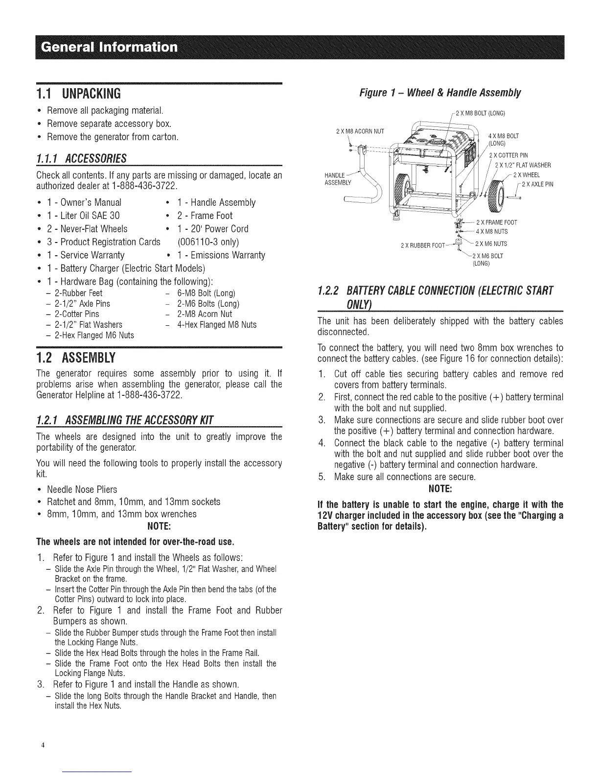
1. Refer to Figure 1 and install the Wheels as follows:
- Slidethe Axle Pin throughthe Wheel, 1/2" FlatWasher,and Wheel
Bracketon the frame.
- Insertthe CotterPinthroughthe Axle Pinthen bendthetabs (ofthe
OotterPins) outward to lock into place.
2. Refer to Figure 1 and install the Frame Foot and Rubber
Bumpers as shown.
- Slidethe RubberBumperstuds throughthe FrameFootthen install
the LockingFlangeNuts.
- Slidethe HexHeadBolts through the holes in the FrameRail.
- Slide the Frame Foot onto the Hex Head Bolts then install the
Locking FlangeNuts.
3. Refer to Figure 1 and install the Handle as shown.
- Slidethe long Bolts through the HandleBracketand Handle,then
install the HexNuts.
Figure 1 - Wheel & Handle Assembly
2 XM8BOLT(LONG)
2 XM8ACORNNUT
ASSEMBLY
4 X M8 BOLT
,(LONG)
2 X COTTER PIN
2 X I/2" FLATWASHER
2 X WHEEL
2 X AXLE PIN
_-'_ ....... 2 X FRAME FOOT
_Z'_ 4X M8NUTS
2 X RUBBER FOOT---_ _ 2 XM6 NUTS
2 XM6BOLT
(LONG)
1.2.2 BATTERYCABLECONNECTION(ELECTR/CSTART
ONLY_
The unit has been deliberatelyshipped with the battery cables
disconnected.
Toconnectthe battery,you will needtwo 8mm boxwrenchesto
connectthe batterycables.(seeFigure16 for connectiondetails):
1. Cut off cable ties securing battery cables and remove red
coversfrom batteryterminals.
2. First,connecttheredcableto thepositive(+) batteryterminal
with the bolt andnut supplied.
3. Makesureconnectionsare secureandsliderubber boot over
thepositive (+) batteryterminal and connectionhardware.
4. Connectthe black cable to the negative(-) battery terminal
with thebolt and nut suppliedand slide rubber boot over the
negative(-) batteryterminal and connectionhardware.
5. Makesure all connectionsaresecure.
NOTE:
If the battery is unable to start the engine,chargeit with the
12V chargerincludedinthe accessory box(see the "Charginga
Battery"section for details).

 Loading...