1.3 EMiSSiONSiNFORMATiON
TheEnvironmentalProtectionAgency (andCaliforniaAir Resource
Board for generators certified to CA standards) requires that
this generator comply with exhaust and evaporative emission
standards.Locatethe emissions compliance decal on the engine
to determinewhatstandardsthe generatormeets,andto determine
which warranty applies.This generatoris certifiedto operateon
gasoline. The emission control system includes the following
components(if equipped):
• Air Induction System
- IntakePipe/ Manifold
- AirCleaner
• FuelSystem
- Carburetor
- FuelTank/Cap
- FuelLines
- EvaporativeVentLines
- CarbonCanister
• IgnitionSystem
- SparkPlug
- IgnitionModule
• ExhaustSystem
- ExhaustManifold
- Muffler
- PulsedAirValve
- Catalyst
2.1 KNOWTHEGENERATOR
Read the Owner'sManual and Safety Rules before operating
thisgenerator.
Compare the generator to Figures 2 through 4 to become
familiarizedwith thelocationsof variouscontrolsandadjustments.
Savethis manualfor future reference.
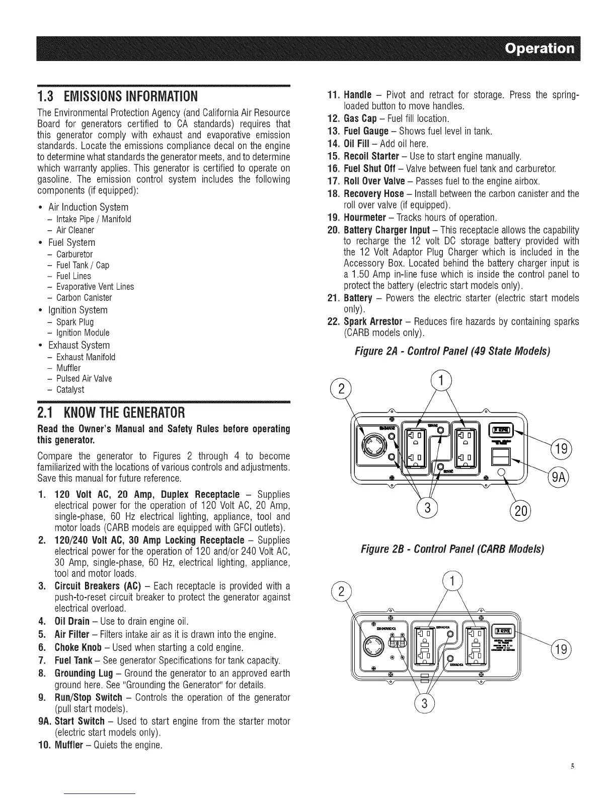
1. 120 Volt AC, 20 Amp, Duplex Receptacle - Supplies
electrical power for the operationof 120 Volt AC, 20 Amp,
single-phase, 60 Hz electrical lighting, appliance, tool and
motor loads (CARBmodelsare equippedwith GFCIoutlets).
2. 120/240 Volt AC, 30 Amp LockingReceptacle - Supplies
electricalpowerfor the operationof 120 and/or240 VoltAC,
30 Amp, single-phase,60 Hz, electrical lighting, appliance,
tool andmotor loads.
3. CircuitBreakers (AC)- Eachreceptacleis providedwith a
push-to-resetcircuit breakerto protectthe generatoragainst
electricaloverload.
4. Oil Drain- Useto drainengineoil.
5. Air Filter- Filtersintakeair as it is drawn intothe engine.
6. ChokeKnob- Usedwhen starting a cold engine.
7. FuelTank- SeegeneratorSpecificationsfor tank capacity.
8. GroundingLug - Groundthe generatorto an approvedearth
groundhere.See"GroundingtheGenerator"for details.
9. Run/Stop Switch- Controls the operationof the generator
(pull start models).
9A. Start Switch - Used to start engine from the starter motor
(electricstart modelsonly).
10. Muffler- Quietsthe engine.
11. Handle - Pivot and retract for storage. Press the spring-
loadedbuttonto move handles.
12. GasCap- Fuelfill location.
l& FuelGauge- Showsfuel levelin tank.
14. Oil Fill- Add oil here.
15. Recoil Starter - Useto start enginemanually.
15. FuelShut Off - Valve betweenfuel tank and carburetor.
17. Roll OverValve- Passesfuel to the engineairbox.
18. Recovery Hose- Installbetweenthe carbon canister andthe
roll overvalve (if equipped).
19. Hourmeter- Trackshoursof operation.
20. Battery ChargerInput - This receptacleallowsthe capability
to rechargethe 12 volt DO storage battery provided with
the 12 Volt Adaptor Plug Charger which is included in the
Accessory Box. Located behindthe battery charger input is
a 1.50 Amp in-line fuse which is inside the control panelto
protectthe battery(electricstart models only).
21. Battery - Powersthe electric starter (electric start models
only).
22. Spark Arrestor - Reducesfire hazardsby containing sparks
(CARBmodels only).
Figure 2.4 - Contro/ Panel (49 State Models)
Figure 2B - Contro/ Panel (CARB Models)

 Loading...