EasyManua.ls Logo

General 90-270 User Manual

General 90-270
36 pages
To Next Page IconTo Next Page
Page #1 background imageLoading...
Page #1 background image
Heavy-duty one-piece frame, designed for
added stability, requires no further
assembly.
Precision-balanced, rubber laminated,
cast-iron wheels, mounted on two
heavy-duty ball bearings.
Large, ribbed cast-iron table with heavy-
duty one-piece trunnion for 0 - 45° tilting,
for bevel cuts.
Convenient blade tension adjustment
hand wheel.
A tension scale allows the operator to
adjust the tension for different blade
widths.
Foot brake for quick blade stoppage after
machine shut-off.
4” dust collection port for easy hookup to
a dust collector.
Powerful totally enclosed fan cooled
(T.E.F.C.) industrial motor.
Magnetic safety switch with emergency
stop button for added safety.
Tri-Axis bearing guides.
WHEEL SIZE
18” (450 MM)
WHEEL SPEED
980 RPM - #90-270
1010 RPM - #90-270 HD
WIDTH OF WHEEL
1 1⁄8” (28.5 MM)
MIN/MAX BLADE WIDTH
1⁄4” TO 1” (6.3 TO 25.4 MM)
BLADE LENGTH
153” (3886 MM) - #90-270
168 1⁄2” (4280 MM) - #90-270 HD
BLADE SPEED
4460 FPM (1338 MPM) - #90-270
4700 FPM (1410 MPM) - #90-270 HD
MAXIMUM DEPTH OF CUT
12” (305 MM) - #90-270
18” (457 MM) - #90-270 HD
MAXIMUM WIDTH OF CUT
17 1⁄4” (438 MM)
TABLE SIZE
24” X 19 1⁄2” (610 X 500 MM)
TABLE TILT
TO 45° (OUT)
TABLE HEIGHT
35 1⁄2” (902 MM)
MOTOR
- #90-270
M1 - 3 HP, 220 V, 1 PH, 19 A
M2 - 3 HP, 220/440 V, 3 PH, 8/4.6 A
M3 - 3 HP, 600 V, 3 PH, 2.9 A
MOTOR
- #90-270HD
M1 - 5 HP, 220 V, 1 PH, 23 A
M2 - 5 HP, 220/440 V, 3 PH, 13.3/7.6 A
M3 - 5 HP, 600 V, 3 PH, 4.8 A
WEIGHT
616 LBS (280 KG) - #90-270
710 LBS (323 KG) - #90-270 HD
REVISION 1 - FEB 04/08
© COPYRIGHT GENERAL INTERNATIONAL 02/2008
Question and Answer IconNeed help?

Do you have a question about the General 90-270 and is the answer not in the manual?

General 90-270 Specifications

General IconGeneral
BrandGeneral
Model90-270
CategorySaw
LanguageEnglish

Summary

FEATURES & SPECIFICATIONS

GENERAL® INTERNATIONAL WARRANTY

Warranty Disclaimer

Information and specifications may change; consult retailer for doubts.

Rules for Safe Operation

ELECTRICAL REQUIREMENTS

Electrical Connections

Recommends manual circuit breaker, locally approved wire, and 3-prong plug.

Grounding Instructions

Reduces shock risk via grounding wire and properly installed, grounded outlet.

Circuit Capacity

Ensure circuit wires handle amperage draw; consult electrician if unsure.

Extension Cords

Use 3-wire cords with grounding plug; check gauge suitability for amperage.

IDENTIFICATION OF MAIN PARTS AND COMPONENTS

Front View

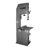
Identifies main parts visible from the front of the bandsaw.

Rear View

Identifies main parts visible from the rear of the bandsaw.

UNPACKING

List of Contents

Lists all items expected in the package upon delivery.

Additional Requirements for Set Up

Lists additional tools and personnel needed for assembly.

Lifting and Handling the Machine

Provides safety guidelines and weight considerations for moving the bandsaw.

PLACEMENT WITHIN THE SHOP / ESTABLISHING A SAFETY ZONE

Placement Within the Shop

Guidance on positioning the bandsaw for safe operation and workflow.

Establishing a Safety Zone

Recommendations for marking a clear safety area around the machine.

CLEAN UP

ASSEMBLY INSTRUCTIONS

Installing the Hoisting Eyebolt

Steps for attaching the hoisting eyebolt to the bandsaw.

Preparing Table Installation

Steps to prepare the bandsaw for table mounting.

Installing the Table

Instructions for mounting the table onto the bandsaw.

Installing the Dust Port

Guide for attaching the dust collection port to the bandsaw.

Repositioning the Foot Brake

Adjusting the foot brake pedal after shipping.

BASIC FUNCTIONS OF THE UNIT

BASIC ADJUSTMENTS AND CONTROLS

Connecting to a Power Source

Safety precautions and steps for connecting the bandsaw to power.

Magnetic Switch

Explanation of the magnetic switch for safety and power surge protection.

Foot Brake

How to use the foot brake for blade immobilization.

RECOMMENDED ADJUSTMENTS

Tilting the Table

Instructions for adjusting the table angle for bevel cuts.

Adjusting the 90 Degree Table Stop and Re-aligning the Angle Pointer

Calibrating the 90-degree stop and angle pointer for accuracy.

Removing/Installing the Blade

Steps and considerations for changing the bandsaw blade.

BLADE SELECTION

Blade Installation

Guidance on proper blade installation and orientation.

ADJUSTING BLADE TENSION

BLADE TRACKING ADJUSTMENTS

Blade Clearance

How to ensure proper clearance between blade and bearings.

Blade Tracking Adjustments

Steps to align the blade for optimal tracking on the wheels.

ADJUSTING THE BLADE GUARD FOR DEPTH OF CUT

ADJUSTING THE UPPER AND LOWER BLADE GUIDES AND SUPPORT BEARINGS

Positioning the Upper/Lower Blade Guides

How to set the blade guides for accurate cuts.

Positioning the Upper/Lower Support Bearings

Adjusting support bearings for blade stability and preventing damage.

OPERATING INSTRUCTIONS

Checklist Before Starting

Essential checks to perform before operating the bandsaw.

CONNECTING TO A DUST COLLECTOR

OPERATIONS STEP-BY-STEP

TO STOP THE MACHINE

INSTALLING/USING THE RIP FENCE

LUBRICATION

PERIODIC MAINTENANCE

REQUIRED MAINTENANCE

Replacing the Bandsaw Blade

Symptoms indicating when a blade replacement is necessary.

Replacing the Upper and Lower Blade Guides/Support Bearings

Steps for replacing upper/lower blade guides and support bearings.

Replacing the Wheel Tire

Guidance on replacing worn or damaged wheel tires.

Related product manuals