16
BLADE TRACKING ADJUSTMENTS
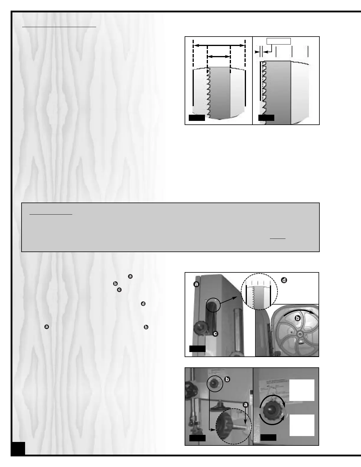
Ideally, the blade should stay relatively centered on both
the upper and lower wheels (Fig. 6).
Due to natural variations in castings, blade thickness or
density and tire wear, absolute perfect centering align-
ment is rarely attainable. A slight misalignment of the
blade on the wheels is inevitable and as long as it is kept
to a minimum (following the steps listed below) will not hin-
der the performance of the saw.
This misalignment is controlled and kept to a minimum pri-
marily by adjusting the tilt angle of the upper wheel.
When adjusting blade tracking to center the blade on the
wheels and assuming that perfect centering is not attain-
able, it is preferable to have the blade slightly off-center
towards the front of the wheels rather than towards the rear because the teeth on most band saw blades have alter-
nating hook (one inner, one outer) – therefore if the blade is centered too far back on the wheel (or if the blade ten-
sion is too tight), inner hooked teeth will dig into the wheel tire and cause premature wear of the tire.
Nonetheless, to avoid having the blade come off of the wheels on it’s own during operation, the front edge of the
blades teeth should never be any closer than 3mm (1/16”) from the front edge of the wheel (Fig 7).
3 MM - 1/16"
Fig. 6 Fig. 7
1. Open the upper wheel cover door
then rotate the
wheel slowly forward by hand and check (through
the window .of the upper wheel ) the position of the
blade on the wheel.
The blade should remain as cen-
tered as possible on the wheel as it turns . (Fig. 8)
2. If the blade tracking must be adjusted, loosen the jam
nut on the tracking adjustment knob , using a
14 mm open end wrench, then turn the knob: (Fig. 9)
A) Clockwise if the blade moves toward the front of
the wheel (Fig. 10). This tilts the top of the wheel to
the back and moves the blade toward the center.
B) Counter- clockwise If if the blade moves toward
the back edge (Fig. 10). This tilts the top of the
wheel to the front and moves the blade toward
the center.
Note: Turn the tracking knob in 1/2 turn increments, re-check
and adjust again as needed.
3. With the tracking set, tighten the jam nut to secure the
tracking adjustment knob in place.
Turn CW if
blade
moves to
front
Fig. 8
Turn CCW
if blade
moves to
back
Fig. 9
Fig. 10
BLADE CLEARANCE
Note: As previously stated, when performing blade installation, removal, tensionning or tracking, maximum clearance
between the blade and both upper and lower bearing assemblies is required to minimize friction, which would be
damaging to the blade. Refer back to page 13 and follow the instructions for “BLADE CLEARANCE” before performing
blade tracking adjustments.