10
3.
P
osition the dust port on the side panel, its open
end facing downward , and attach it using the
four screws. Then, put the blade guard back in
place .
REPOSITIONNING THE FOOT BRAKE
To limit the potential for damage in transport, this
bandsaw is shipped from the factory with the the foot
brake pedal tilted up . To be operational, the pedal
must be tilted down as follows:
1. Loosen the bolt that attaches the foot brake pe-
dal to the mounting bracket using a 14 mm open
end wrench .
2. Swivel the foot brake pedal manually .
3. Tighten the bolt to lock the foot brake pedal in
position.
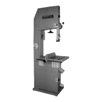
BASIC FUNCTIONS OF THE UNIT
This 18" wood cutting bandsaw is supplied with a 1/2" wide general purpose blade and is designed to accommo-
date blade widths from 1/4" to 1". Ideal blade length for the model 90-270 is 153" (3886 mm) and ideal blade length
for the 90-270HD is 168 1/2" (4280 mm).
Note: Generally speaking, because the upper wheel height is somewhat adjustable (to allow for blade tensioning), a blade
length variation of plus or minus 1/2" from the “ideal blade length” can be accommodated on both models.
Maximum inboard width of cut (space between t h e
blade and the body of the saw ) is 17 1/4 " for both
models.
For cutting thicker stock or for resawing, the maximum
depth of cut (or max. workpiece height ) is 12 " for
the 90-270 and 18" for the 90-270HD.
A sturdy, cast iron, adjustable rip fence is supplied
to serve as a straightedge to guide the workpiece for
longer rip cuts. The fence can easily be removed and
set aside when not required, for example when mak-
ing curved cuts.