EasyManua.ls Logo

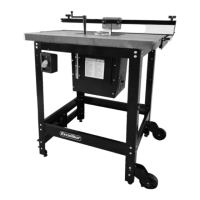
General Excalibur 40-200C

General Excalibur 40-200C
38 pages
To Next Page IconTo Next Page
Loading...
SETUP & OPERATION MANUAL
MODEL
#
40-200C
DELUXE ROUTER TABLE KIT
(Floor model)
© Copyright General® International
FEATURES
Heavy-duty massive router lift with 9 1/4” x
11 3/4” aluminum top plate.
Stable 4 post/lift screw design & chain drive
lifting system controlling all 4 corners simul-
taneously.
Fits all fixed base router motors*.
Smooth above-the-table adjustment mech-
anism for fast tool changes & precision bit
setting.
Available with table in either cast-iron (40-
200C), MDF (40-200M) or Phenolic (40-200P).
Stand made of tubular steel, includes,
mobility kit, adjustable leveling feet and
easy access on/off safety switch with
removable lock-out key.
Fence has 2 1⁄4” dust collection outlet and
adjustable scales.
Under table steel dust enclosure with
access door, adjustable air vent, power
cord grommet and 4” dust port with 2 1⁄4”
branch inlet to the fence. Includes 2 1⁄4”
dust hose and 2 hose clamps.
Some router models may require reducer
collars/adaptors.
*
SPECIFICATIONS
OVERALL DIMENSIONS
35 1/2” X 24” X 41 (902 X 609 X 1041 MM)
TABLE SIZE/HEIGHT
32” X 24 (812 X 609 MM) /36 1/2” (927 MM)
FENCE SIZE (EACH)
3” X 17 3/4” X 3/4” (76 X 451 X 19 MM)
MAXIMUM FENCE TRAVEL
9” (229 MM)
DUST OUTLET
4” (102 MM)
DISTANCE BETWEEN T-SLOT & SPINDLE CENTER
3/4”: 5 5/8” (143 MM)
3/8”: 7 3/16” (183 MM)
DISTANCE FROM SPINDLE
CENTER TO FRONT EDGE OF TABLE
12” (305 MM)
T-SLOT DIMENSIONS
3/4” X 3/8” (19 X 10 MM) /
3/8” X 1/4” (10 X 7 MM)
ROUTER INSERT PLATE
9 1/4” X 11 3/4” (235 X 298 MM)
TABLE OPENING SIZES - DIAMETER
PLATE: 3 3/4” (95 MM)
INSERT RING: 1 1/2” (38 MM)
NET WEIGHT (40-200C MODEL)
179 LBS (81 KG)
Question and Answer IconNeed help?

Do you have a question about the General Excalibur 40-200C and is the answer not in the manual?

General Excalibur 40-200C Specifications

General IconGeneral
BrandGeneral
ModelExcalibur 40-200C
CategoryPower Tool Accessories
LanguageEnglish

Summary

GENERAL INTERNATIONAL WARRANTY

Limited Lifetime Warranty

Details warranty coverage for defects in workmanship or material for the tool's life.

Standard 2-Year Limited Warranty

Covers commercial, industrial, or educational use for two years.

To file a Claim

Outlines the warranty claim process, including required documentation.

Rules for Safe Operation

PLACEMENT WITHIN THE SHOP ESTABLISHING A SAFETY ZONE

PLACEMENT WITHIN THE SHOP

Guidelines for positioning the router table for optimal use and safety.

ESTABLISHING A SAFETY ZONE

Recommendations for creating a safe operational area around machinery.

UNPACKING

LIST OF CONTENTS - 40-085 STAND (40-200)

Itemized list of components for the 40-085 stand package.

LIST OF CONTENTS - 40-080 ROUTER FENCE (40-200)

Itemized list of components for the 40-080 router fence package.

LIST OF CONTENTS 40-125 ROUTER LIFT

Itemized list of components for the 40-125 router lift package.

LIST OF CONTENTS 40-130 DUST COLLECTION KIT

Itemized list of components for the 40-130 dust collection kit.

LIST OF CONTENTS - CAST-IRON TABLE

Itemized list of components for the cast-iron table package.

ASSEMBLY INSTRUCTIONS - 40-085 ROUTER TABLE STAND

ASSEMBLY INSTRUCTIONS - TABLE 40-07540-04940-045

CLEANING THE CAST-IRON TABLE

Instructions for cleaning the protective coating from the cast-iron table.

INSTALL THE TABLE

Steps for attaching the cast-iron or phenolic table to the stand.

ASSEMBLY INSTRUCTIONS - ATTACH THE STAND TO THE TABLE

ENGAGINGDISENGAGING THE STAND CASTERS

How to operate the caster system to move or immobilize the table.

ASSEMBLY INSTRUCTIONS - #40-080 ROUTER FENCE

ASSEMBLY INSTRUCTIONS - PREPARE THE TABLE FOR ROUTER LIFT

ASSEMBLY INSTRUCTIONS - 40-130 DUST COLLECTION KIT

ASSEMBLY INSTRUCTIONS - MOUNTING A ROUTER

LEVELING AND LOCKING THE ROUTER PLATE

INSERT RING REMOVAL

Procedure for removing the insert ring from the router plate.

INSTALLING THE STARTING PIN

How to install the starting pin for freehand or template routing.

BASIC ADJUSTMENTS & CONTROLS

ADJUSTING THE FENCE ALONG THE RAILS

How to slide and secure the fence along the table rails.

ADJUSTING THE SLIDING SCALE ON THE RAILS

Method for adjusting the fence scale to desired measurement points.

ADJUSTING THE FENCE FACES

Instructions for adjusting removable fence faces for different workpiece sizes.

CONNECTING THE ROUTER TO THE SAFETY SWITCH

USING THE SAFETY SWITCH

How to connect and use the safety switch for router power control.

CONNECTING TO A DUST COLLECTOR

Guidance on connecting a dust collector to the table's dust outlet.

OPERATING INSTRUCTIONS

BEFORE STARTING

Essential checks and preparations before operating the router table.

USING THE SPACER BARS FOR JOINTING

How to use spacer bars to offset the outfeed fence for jointing.

JOINTING

Step-by-step guide for performing jointing operations on wood pieces.

GROOVE CUTTING

Instructions for cutting grooves or beads into the face of a board.

PROFILE CUTTING

How to perform profile cutting using a bit with a guide bearing.

TENSIONING THE DRIVE CHAIN

Procedure for adjusting drive chain tension on the router lift.

RECOMMENDED OPTIONAL ACCESSORIES