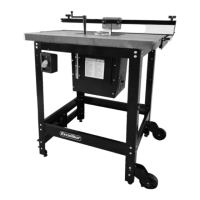
3. With the router plate leveled to the table, lock the plate
in place using the two supplied hex socket head
screws C in the threaded holes on both sides of the plate.
C
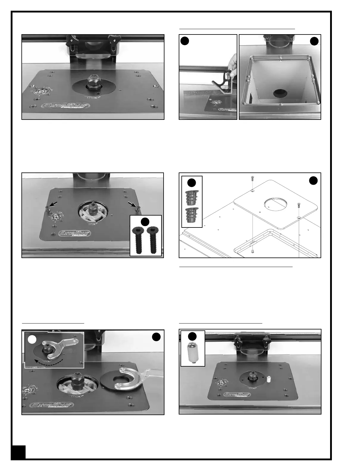
Insert the two pins of the wrench in the two holes on
the insert ring then turn clockwise to unlock the ring,
A and lift the insert ring up and out of the table inser-
tion, B.
INSERT RING REMOVAL
INSTALLING THE STARTING PIN
Install the starting pin A into the threaded hole on the
router plate as shown. The starting pin can be used as
needed for freehand or template routing only.
A
22
4. The routers collet should now be protruding out from
the top plate. This will facilitate tool (router bit)
changing from above the table eliminating the
need to remove the router lift system from the table
to access the collet.
A
B
LEVELING AND LOCKING THE ROUTER PLATE
1. Using a straightedge check that the router plate is
level with the main table, A.
2. Adjust the 10 leveling screws B in the table opening
as needed to level the plate on all four sides. (If
needed, refer back to the instructions on page 18.)
A
B
For #40-049 MDF table (for #40-200M) only: From the
underside of the table, thread the 2 supplied wood nuts
D onto the screws, as shown in E.
D
E
 Loading...