44-00-0297 SHERLOCK102/202 REV. 4.1 05-02-15
11
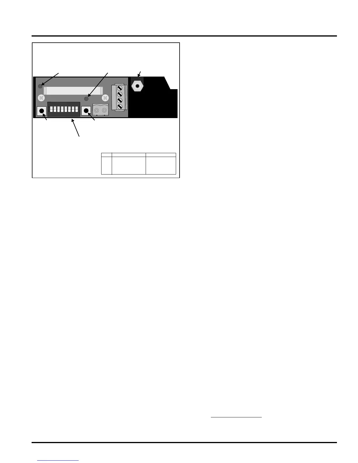
IR SENSOR
OPERATION
BEFORE CONTINUING, DON'T FORGET TO WRITE
DOWN THE START UP DATE ON THE FRONT OF
EACH SENSOR. FAILURE TO DO SO COULD VOID
THE WARRANTY.
Infrared Sensor components description and use. (Please see
44-0295 Infrared sensor Manual for more information)
Dip Switch -- Switches 1 to 8 are set to off at the factory.
This is the standard dip switch setting for normal operation
Switches 1, 2, and 3 - Switches 1, 2, and 3 are for communica-
tions port addressing.
Switch 4 - For auto long term zero compensation. It will recali-
brate up to 10 ppm every 7 days. No more than 100 ppm between
manual calibrations. Disable for low level detection.
On zero Compensation SW4 = OFF
Disabled SW4 = ON
Switch 5 - For fi eld testing at a set level.
Normal SW5 = OFF
Fixed 200 ppm output SW5 = ON
Switch 6 - For factory calibration.
Normal SW6 = OFF
Default Factory setting SW6 = ON
Switch 7 - For setting an offset to change from a Sherlock/Wizard
control system sensor to a stand-alone sensor BAS signal.
Sherlock/Wizard SW7 = OFF
Standalone (4-20mA) SW7 = ON
Switch 8 - Not used
Push buttons - Located just on either side of the DIP
Switches.
Push button 1 It is used for testing the sensor with a 200 ppm
false signal. Dipswitch 5 can be used for the same function.
Push button 2 It is used for sensor calibration and is used in
conjunction with LED 2
Light Emitting Diodes (LED)
LED L1 - LED L1 will indicate if the sensor microprocessor is
operating and if the sensor if the sensor is in test mode. When
the microprocessor goes through start-up, it will turn on L1 and
keep it on unless switch 5 is on or pushbutton 1 is depressed.
Status Condition
Off Sensor is not powered up.
Microprocessor detects an error in
the sensor hardware.
Microprocessor Failure
ON Steady Sensor is operating properly.
ON Flashing Switch 5 is set to on or pushbutton 1
is depressed or microprocessor error.
LED L2 - LED L2 is used for zero calibration. When pushbut-
ton 2 is pressed, LED 2 will light after 8 seconds and turn off
once the button is released.
Status Condition
Off Normal operation
ON Steady Factory Calibrated Setting. Turn
switch 6 off
ON Flashing Microprocessor error. Call factory.
Potentiometers. If you have an old style sensor with a housing
that opens to show the entire inside of the sensor, please call
Genesis for a specifi c manual or technical advice before making
any changes to the potentiometer positions. The Sherlock IR
Sensor contains several potentiometers used in factory testing
and calibration and turning them without factory guidance can
ruin the sensor. For all new IR sensors these potentiometers are
located inside the main part of the housing and there should be
no need to open this part of the sensor to make any adjustments.
It is not recommended to do so as this could void the warranty
and cause permanent damage to the sensor.
SENSOR EMERGENCY RESET TO ORIGINAL FAC-
TORY SETTING
Sensor Reading not keeping steady
If the sensor reading is floating, ie. not staying at “0”, the some-
times happens when the sensor push button calibration is done
before the recommended burn in time of 3 hours, or if there is
bad data in the sensor microprocessor, a factory reset may be
necessary.
WARNING! FOLLOW INSTRUCTIONS EXACTLY!
1) Flip Switch 6 Up, “Factory Calibration”.
2) Hold Down Calibration Push Button. If LED is ON, it may
go out when the button is pressed. Hold the button down for at
least 8 seconds. The LED will come on.
3) Release the button.
4) Wait 2 Minutes
5) Switch Dip Switch 6 Off.
6) Disconnect Power From the Sensor.
7) Re-Connect Power.
8) Wait a minimum of 3 hours (more is preferable).
9) Attempt the Push Button procedure again.
10) Do control calibration
ON
1 2 3
4
5 6 7 8
1
2
3
4
P1
SIG OUT
STATUS
CALIB.
GENESIS INT’L INC 01-0224
VER .1.0 IROUTB 07-25-02
CALIBRATION
PUSH BUTTON
ARTIFICIAL 200 PPM
PUSH BUTTON
CALIBRATION LED
LED 2
STATUS LED
LED 1
LOOSEN SCREW AND SLIDE LOWER PLATE DOWN TO ACCESS
WIRING AND CALIBRATION BUTTON AND OTHER FEATURES
FIGURE 7
DIPSWITCHES
Connector P1
Sherlock 3-Wire 4 - 20 MilliAmp
P1-4 Ground V return
P1-3 +12V DC in V+in(10-36VDC)
P1-2 Ground MA return
P1-1 Signal Output MA output
(Not Used)
GAS CALIBRATION
INTAKE
 Loading...