17
For Help, call 1-800-35-GENIE or visit www.geniecompany.com
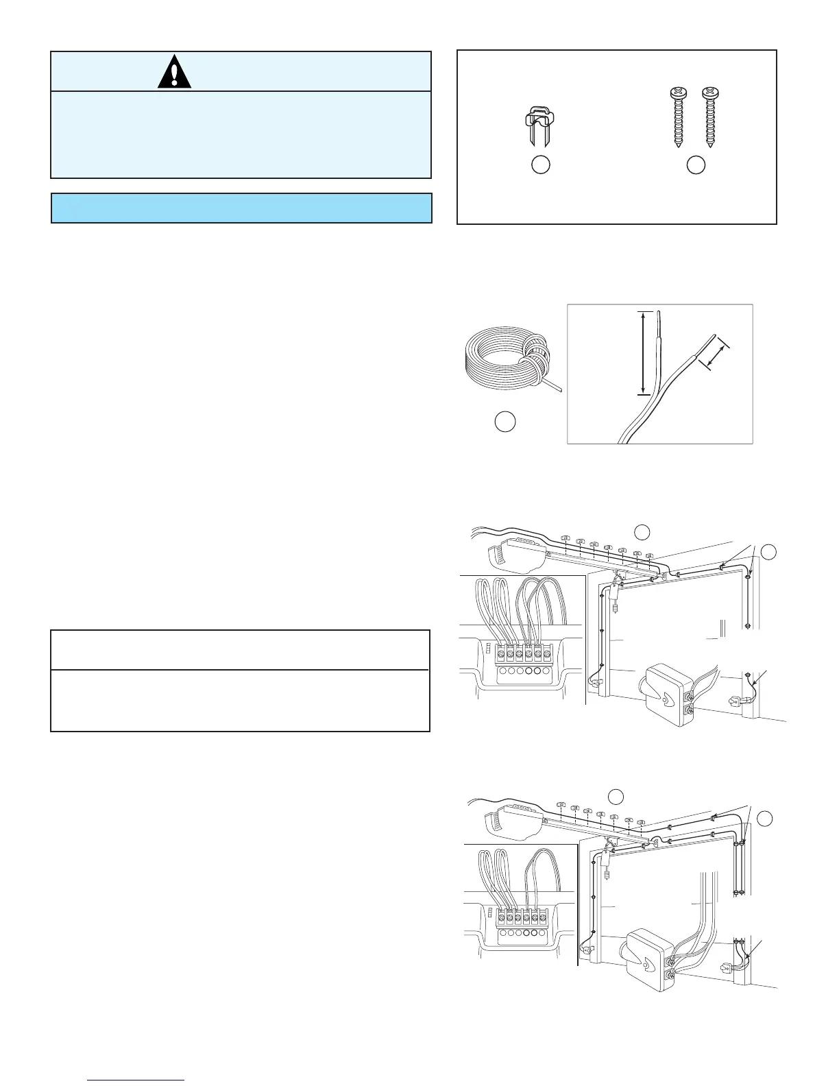
C Install Safe-T-Beam® Wiring (Figure 28):
• Route Wire and Insulated Staples
(Figure 29 and Figure 30).
–Securely fasten Wires with Insulated Staples as
you go. Staples should be snug only.
–Wires between garage wall and Power Head should
be run on top of Rail and underneath Wire Clips.
• Attach Wires to Safe-T-Beam® Sensors.
–Split and strip Wire ends to be connected as shown.
–Loosen Terminal Screws.
– Insert each Wire under flat plate and tighten Screw.
It does not matter which Wire, white or striped, goes
on which Terminal.
• Attach Wires at Power Head.
–Wires are connected to Terminals #2 and #3 on
Power Head Terminal Block. It does not matter which
Wire, white or striped, goes on which Terminal.
• Check the following.
– Ensure that no part of door or its hardware is in path
between Source or Sensor Lenses.
• Ensure that tops of Lenses are between 5" – 6" above
floor. Brackets are flexible and can be adjusted slightly
if needed.
CAUTION
Staples which are too tight may cut or pinch Wires. Cut or
pinched Wires can cause the Safe-T-Beam® System to stop
working. When installing the Insulated Staples, make sure
you fasten them only as tightly as needed to hold the
Wire securely.
NOTE
The Safe-T-Beam® alignment check will be performed
following connection to electrical power.
Do Not plug in yet!
OPEN RED PARTS BAG