Section 6 • Schematics September 2016
REV B
6 - 2 GRC Part No. 227123
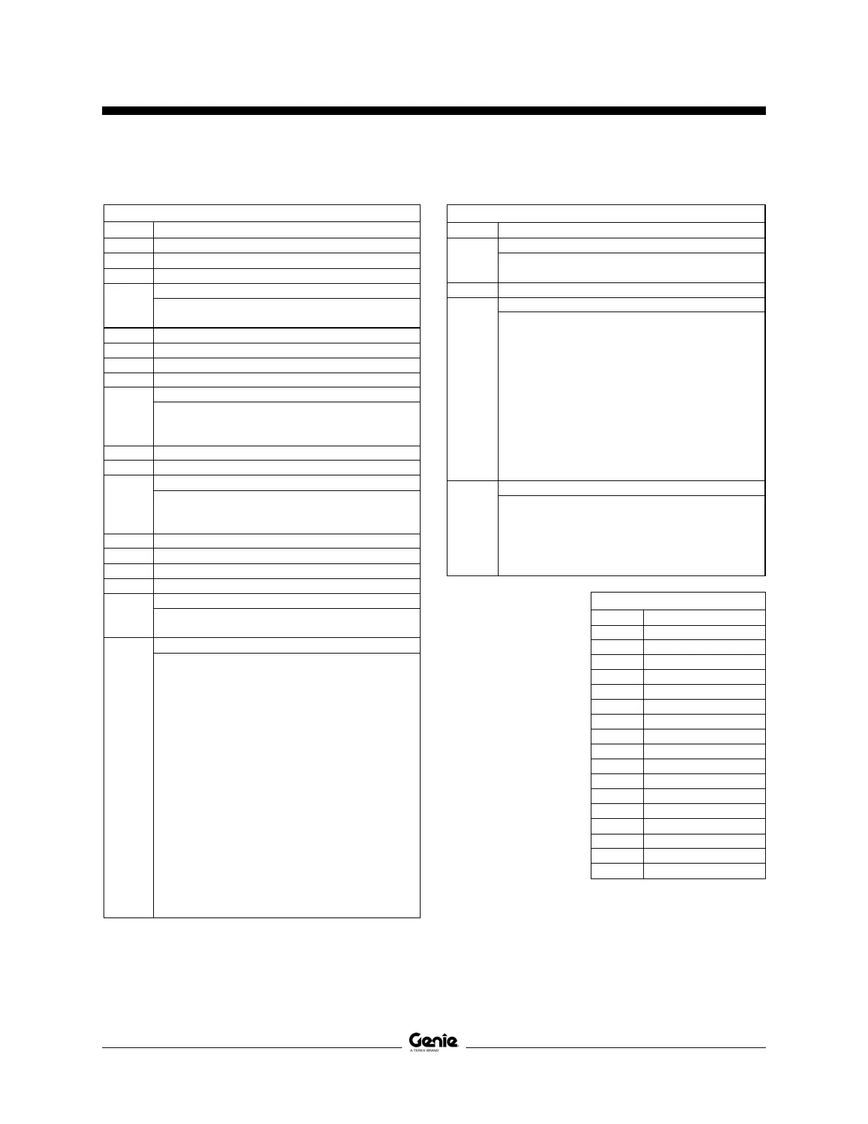
Electrical Component and Wire Color Legends
ELECTRICAL COMPONENT LEGEND
Item Description
B5 Battery
CB2 Circuit breaker, 7A
CON1 Contactor, Motor controller power, NOHC
Diode
D
D1 = Motor controller enable, 3A
D2 = Motor controller B+, 3A
EN4 Enclosure - AC outlet box
F6 Fuse, 275A
FB Flashing beacons
GND Ground
Horn or alarm
H
H1 = Horn
H2 = Automotive-style horn (option)
H5 = Multifunction alarm
JC9 Joystick controller
KS1 Key switch
Limit switch
LS
LS6 = Platform down
LS7 = Pothole
LS8 = Pothole
M5 Hydr aulic power unit
NC Normally closed
NCHO Normally closed held open
NOHC Normally open held closed
Power switch
P
P1 = Emergency Stop button at ground controls
P2 = Emergency Stop button at platform controls
Quick disconnect
QD
QD1 = Battery quick disconnect
QD3 = Control cable to ground
QD4 = Control cable to platform
QD30 = AC plug
QD31 = GCON ECM, ground and platform controls
QD32 = GCON ECM, switches and sensors
QD33 = GCON ECM, function manifold
QD34 = Power buss, switches and sensors
QD35 = Ground buss, switches and sensors
QD36 = Pothole guard switches
QD37 = Down limit switch
QD38 = Level sensor
QD39 = Ground buss, function manifold
QD40 = Drive reverse coil, Y5
QD41 = Drive forward coil, Y6
QD42 = Steer right coil, Y3
QD43 = Steer left coil, Y4
QD44 = Platform up coil, Y8
QD47 = Platform controls PCB, power/signal in
QD48 = Platform controls PCB, E-Stop and alarm
QD49 = Platform controls PCB, joystick
ELECTRICAL COMPONENT LEGEND cont.
Item Description
Resistor
R
R27 = Resistor 25 Ohm, 25W (QS retail)
R30 = Resistor, 200 Ohm, 10W
S7 Level sensor
Electronic component
U
U3 = Platform controls printed circuit board
U5 = Electronic control module
U6 = Motor controller
U9 = Battery charger
U13 = Voltage inverter (option)
U47A = Obstruction sensing pad
(hydraulic tank side) (QS retail)
U47B = Obstruction sensing pad
(battery tray) (QS retail)
U47C = Obstruction sensing pad
(steer end) (QS retail)
U47D = Obstruction sensing pad
(ground controls side) (QS retail)
Valve coil
Y
Y3 = Steer right
Y4 = Steer left
Y5 = Drive reverse
Y6 = Drive forward
Y7 = Platform down
Y8 = Platform up
WIRE COLOR LEGEND
Color Description
BK Black
BL Blue
BL/BK Blue/Black
BL/OR Blue/Orange
BN Brown
GN Green
GN/WH Green/White
GN/YL Green/Yellow
LT BL Light Blue
OR Orange
OR/BK Orange/Black
OR/RD Orange/Red
RD Red
RD/BK Red/Black
WH White
WH/BK White/Black
YL Yellow
 Loading...