Section 4 • Repair Procedures
REV A
September 2016
4 - 14 GRC Part No. 227123
Function Manifold
Index Schematic
No. Description Item Function Torque
— Coil nut (items E, F and H) .......................................................................................................... 5 ft-lbs / 7 Nm
1 Diagnostic nipple ....................................... A ......................... Testing
2 Check disc ................................................. B ......................... Steer circuit ............................ 18 ft-lbs / 24 Nm
3 Relief valve,
1800 to 3500 psi / 124 to 241 bar ............. C ......................... Lift relief .................................. 20 ft-lbs / 27 Nm
4 Check valve, 10 psi / 0.7 bar ..................... D ......................... Drive circuit............................. 20 ft-lbs / 27 Nm
5 Solenoid valve, 3 position 4 way ............... E ......................... Drive forward/reverse ............. 25 ft-lbs / 34 Nm
6 Solenoid valve, 3 position 4 way ............... F ......................... Steer left/right ......................... 25 ft-lbs / 34 Nm
7 Flow regulator and relief valve,
0.75 gpm / 2.8 L/min,
1500 psi / 103 bar ...................................... G ......................... Steer circuit ............................ 26 ft-lbs / 35 Nm
8 Solenoid valve, 2 position 4 way ............... H ......................... Platform up ............................. 25 ft-lbs / 34 Nm
9 Relief valve,
3500 psi / 241 bar maximum ..................... I .......................... System relief........................... 20 ft-lbs / 27 Nm
4-1
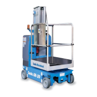
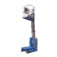
Function Manifold Components
The function manifold is mounted next to the hydraulic power unit.
 Loading...