Section 4 • Repair Procedures
REV A
September 2016
4 - 22 GRC Part No. 227123
Index Schematic
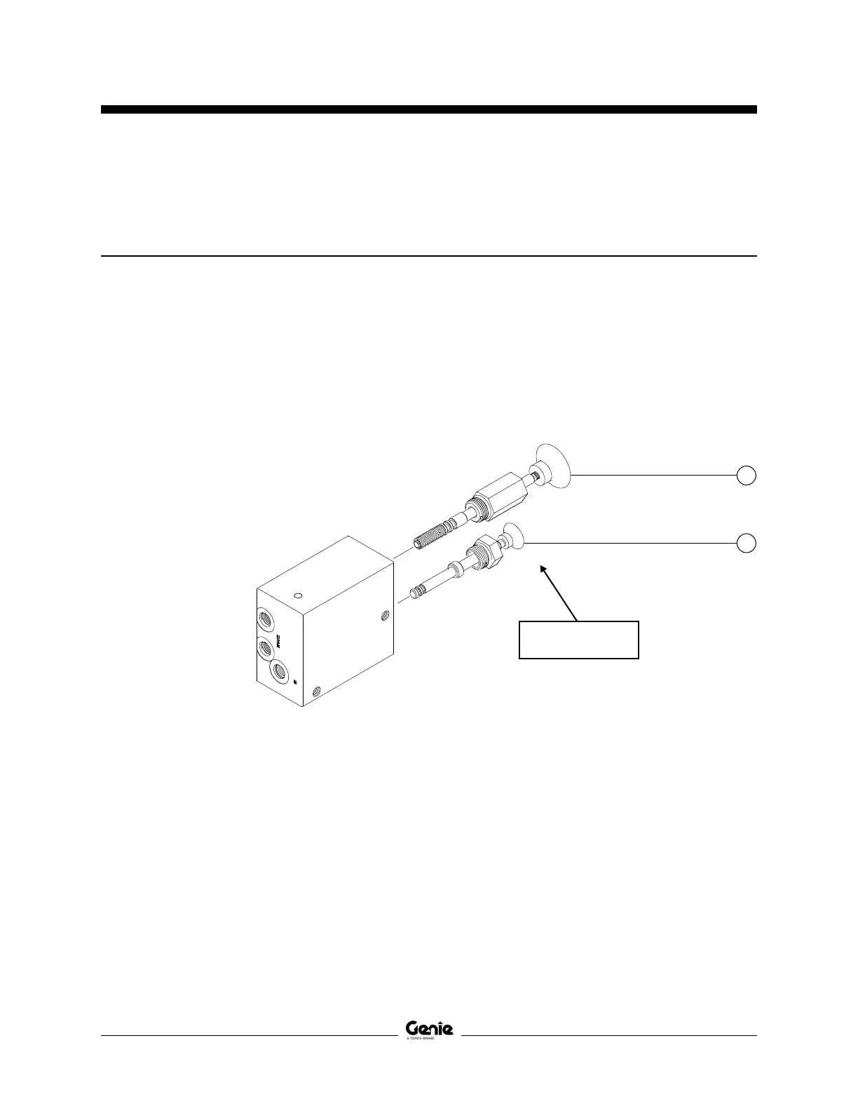
No. Description Item Function Torque
1 Hand pump ....................................... J ................ Manual brake release .............................. 30 ft-lbs / 41 Nm
2 Needle valve, pilot operated ............. K ............... Manual brake release enable .............. 45-50 in-lbs / 5 Nm
Brake Release Hand Pump Components
5-1
Brake Release Hand Pump Components
The brake release hand pump manifold is mounted behind the hydraulic power unit.
J
K
Note: 'alpha' callouts refer
to corresponding notes on
the hydraulic schematic
1
2
 Loading...