Section 4 • Repair Procedures
REV A
September 2016
4 - 40 GRC Part No. 227123
21 Slide the number 4 mast towards the bottom of
the number 3 mast and align the lower number
4 mast access holes to the lower number 3 rivet
holes. Refer to Illustration 9.
22 Working at the top of the number 4 mast,
carefully slide the lower corner wear pads
between the number 4 mast and the number 3
mast. Refer to Illustration 9.
23 Align the rivet holes on the wear pads to the
number 4 mast access holes and to the number
3 mast rivet holes. Refer to Illustration 6.
24 Using the appropriate rivets, securely install the
lower corner wear pads, to the lower half of the
number 3 mast. Refer to Illustration 9.
Note: After installing the first rivet, move and align
the number 4 mast access hole to the second hole
on the wear pad and install the second rivet. Refer
to Illustration 9.
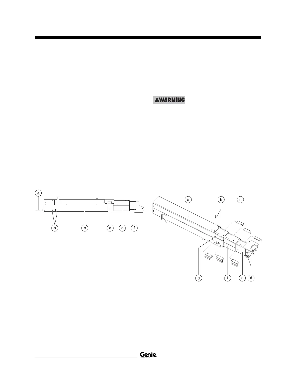
Illustration 9
a wear pad
b rivets
c number 4 mast
d number 3 mast
e number 2 mast
f number 1 mast
25 Attach a lifting strap from an overhead crane
to the mast assembly and carefully rotate the
mast 180°. Set the mast assembly onto the
work table and secure the mast to the table.
Crushing hazard. The mast
assembly could become
unbalanced and fall if not properly
supported.
Note: During installation, the overhead crane strap
will need to be carefully adjusted for proper
balancing.
26 Using Illustration 10 as a guide, stagger the
mast assembly.
27 Slide the lower, inner corner wear pads
between mast sections 1 and 2, 2 and 3, and,
3 and 4. Align the holes on the wear pads to the
rivet holes on the lower half of mast sections 2,
3 and 4. Secure the wear pads into place using
the appropriate rivets. Refer to Illustration 10.
Illustration 10
a number 4 mast
b rivet
c wear pad
d limit switch
e number 1 mast
f number 2 mast
g number 3 mast
MAST COMPONENTS
 Loading...