15
ENGLISH
FSW OP - Opening safety devices contact (terminal 3): The purpose
of the opening safety devices is to protect the leaf movement area
during opening. During opening, in the A-AP-S-E-EP logics the safety
devices reverse the movement of the gate leaves, or stop and restart
the movement when they are released (see advanced programming
in Chpt 5.2). During the opening cycle in logics B and C, they interrupt
movement. They never operate during the closing cycle.
If the Opening safety devices are engaged when the gate is closed,
they prevent the leaf opening movement.
To install several safety devices, connect the N.C. contacts in series
(fig.4).
If no opening safety devices are connected, jumper connect inputs
OP and -TX FSW (fig. 5).
FSW CL - Closing safety devices contact (terminal 4): The purpose of the
closing safety devices is to protect the leaf movement area during
closing. During closing, in the A-AP-S-E-EP logics, the safety devices
reverse the movement of the gate leaves, or stop and reverse the
movement when they are released (see advanced programming
in Chpt 5.2). During the closing cycle in logics B and C, they interrupt
movement. They never operate during the opening cycle.
If the Closing safety devices are engaged when the gate is open,
they prevent the leaf closing movement.
To install several safety devices, connect the N.C. contacts in series
(fig.4).
If no closing safety devices are connected, jumper connect terminals
CL and -TX FSW (fig. 5).
STOP - STOP contact (terminal 5): any device (e.g. a push-button)
which, by opening a contact, is able to stop gate movement.
To install several STOP devices, connect the N.C. contacts in se-
ries.
If STOP devices are not connected, jumper connect the STP and - ter-
minals.
EDGE - EDGE safety device contact (terminal 6): The purpose of the
“edge” safety device is to protect the leaf movement area during
opening/closing against fixed obstacles (pillars, walls, etc.). In all
logics, during opening and closing, the safety devices reverse gate
leaf movement for 2 seconds. If the safety devices operate again
during the 2-seconds reversing time, they STOP movement without
any reversing.
If the Edge safety devices are engaged while the gate is closed or
open, they prevent the leaves movement.
To install several safety devices, connect the N.C. contacts in series
(fig.4).
If edge safety devices are not connected, jumper connect the EDGE
and - inputs. (fig. 5).
– Negative for power supply to accessories (terminals 7 and 8)
+ 24 Vdc - Positive for power supply to accessories (terminals 9 and
10)
Accessories max. load is 500 mA. To calculate absorption values, refer
to the instructions for individual accessories.
TX -FSW - Negative for power supply to photocell transmitters (terminal 11)
If you use this terminal for connecting the negative for supplying
power to the photocell transmitters, you may, if necessary, also use
the FAIL SAFE function (see advanced programming in Chpt 5.2).
If this function is enabled, the equipment checks operation of the
photocells before every opening or closing cycle.
W.L. - Power supply to indicator-light / timed output (terminal 12)
Connect a 24 Vdc - 3 W max indicator-light or timed output, if ne-
cessary, between this terminal and the +24V supply (see advanced
programming in Chpt 5.2).
To avoid geopardising correct operation of the system, do not exceed
the indicated power.
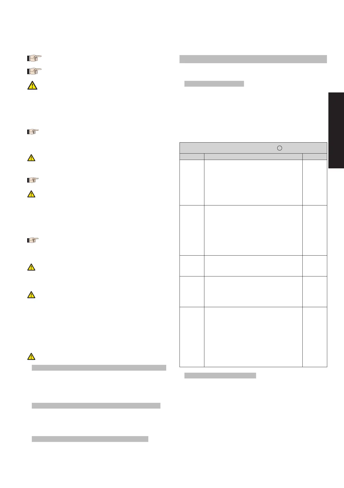
4.5.
Connector J2 - Rapid connection to radio-receiver module
The control unit is designed to house a 5-pin radio-receiver module. To
install, cut out power and fit the module in the appropriate J2 connector
inside the control unit.
This done, observe the radio-receiver instructions for memorystoring the
remote control. When the remote control has been stored, it controls START
just like any command device.
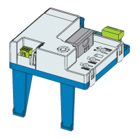
4.6. Connector J6 - Limit-switches rapid connection (fig.2)
This input is intended for rapid connection of the opening and closing
limit-switches designed to stop the leaf, or for start of decelerations or for
braking (see advanced programming in Chpt. 5.2.). In gearmotors with a
built-in control unit, this connection is pre-wired as standard (fig. 2). For leaf
opening direction, see advanced programming in Chpt 5.2.
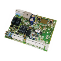
4.7. Connector J3 - Encoder rapid connection (fig.2)
This input is designed for rapid connection of the Encoder (optional). To fit
the encoder on the motor, refer to the relevant instructions.
The presence of the encoder is signalled - when the gearmotor is running
- by the flashing of the “Encoder” LED on the board.
When the encoder is used, the control unit knows the exact position of the
gate while it is moving.
•
•
•
•
•
•
•
•
The encoder controls the adjustments of some of the control unit’s func-
tions in a different way (partial opening or deceleration - see advanced
programming in Chpt 5.2) and as an anti-crushing device.
If the gate strikes an obstacle during opening or closing, the encoder im-
mediately reverses the gate leaf for 2 seconds. If the encoder operates
again during the 2-seconds reversing time, it STOPS movement without
commanding any reversing.
5. PROGRAMMING
To program operation of the automated system, you have to access the
“PROGRAMMING” mode.
Programming is split into two parts: BASIC and ADVANCED.
5.1. BASIC PROGRAMMING
To access BASIC PROGRAMMING, press key F:
if you press it (and hold it down), the display shows the name of the first
function.
if you release the key, the display shows the value of the function that can
be modified with keys + and -.
if you press F again (and hold it down), the display shows the name of
the next function, etc.
when you reach the last function, press F to exit the program, and the
display resumes showing the gate status.
The following table shows the sequence of functions accessible in BASIC
PROGRAMMING:
BASIC PROGRAMMING F
Display Function Default
LO
FUNCTION LOGICS (see tab. 3/a - h):
A
=Automatic
AP
=“Stepped” automatic
S
= “Safety” Automatic
E
= Semi-automatic
EP
= “Stepped” Semi-automatic
C
= Dead-man
b
= “B” Semi-automatic
bC
= Mixed Log. (
b
opening /
C
closing)
EP
PA
PAUSE TIME:
This has effect only if the automatic logic was
selected. Adjustable from
0
to
59
sec. in one-
second steps.
Subsequently, display changes to minutes and
tens of seconds (separated by a point) and time
is adjusted in 10-second steps, up to the maximum
value of
4.1
minutes.
E.g. if the display shows
2.5
, pause time is 2 min.
and 50 sec.
2.0
F0
FORCE:
Adjusts Motor thrust.
01
= minimum force
50
= maximum force
50
d1
OPENING DIRECTION:
Indicates the gate opening movement and makes
it possible not to change the motor and limit-switch
connections on the terminal board.
-3
= Right-hand opening movement
3-
= Left-hand opening movement
-3
St
GATE STATUS:
Exit from programming and return to gate status
viewing.
00
= Closed
01
= Now opening
02
= Stopped
03
= Open
04
= Pause
05
= “FAIL SAFE” tripped (chpt. 5.2)
06
= Now closing
07
= Now reversing
08
= Photocells tripped
5.2. ADVANCED PROGRAMMING
To access ADVANCED PROGRAMMING, press key F and, as you hold it
down, press key +:
if you release key + , the display indicates the name of the first function.
if you release key F too, the display shows the value of the function that
can be modified with keys + and -.
if you press key F (and hold it down), the display shows the name of the
next function, and if you release it, the value that can be modified with
keys + and - is shown.
when you reach the last function, press F to exit the program, and the
display resumes showing the gate status.
The following table shows the sequence of functions accessible in ADVAN-
CED PROGRAMMING:
•
•
•
•
•
•
•
•