9.3 GV-VS12
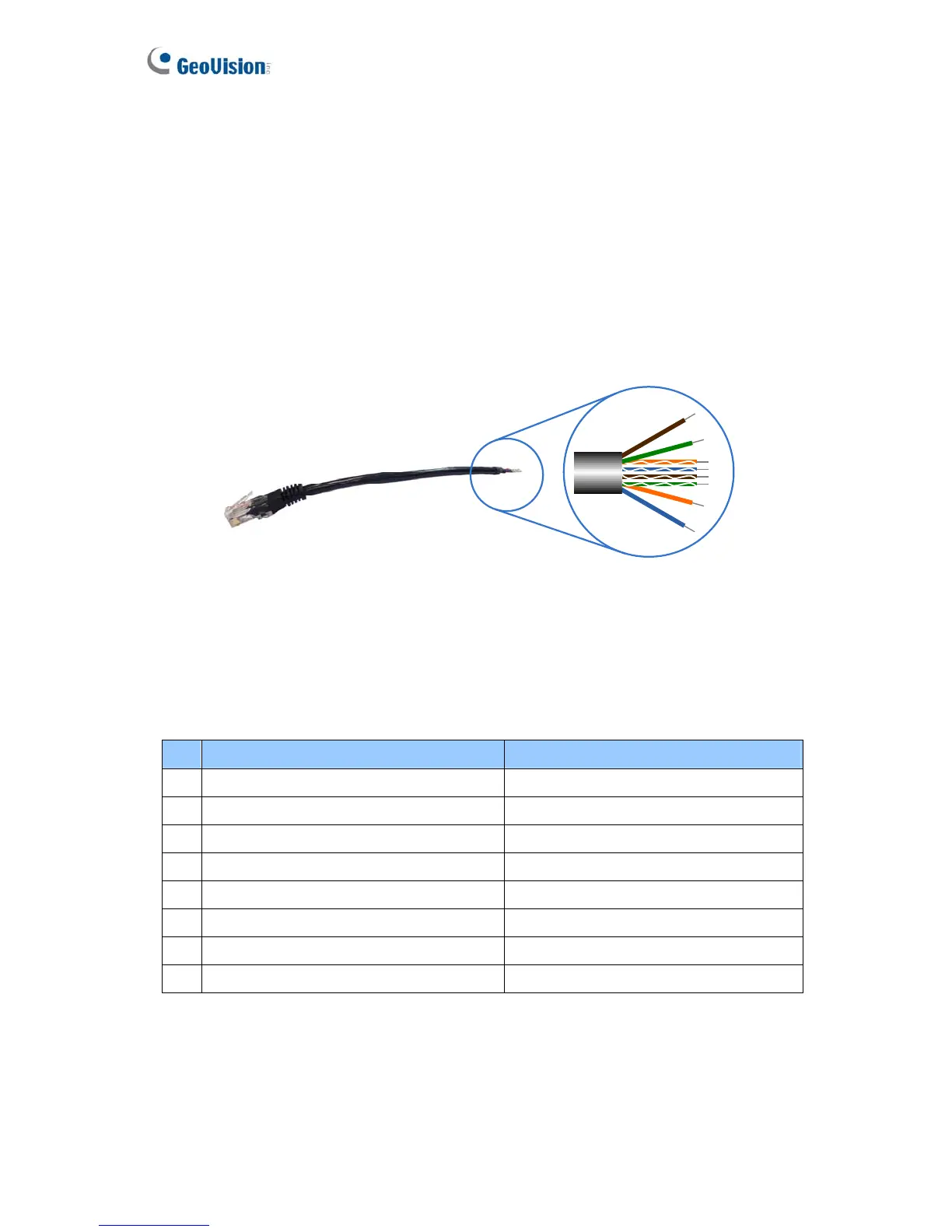
Owing to the model size, GV-VS12 provides I/O Cable with RJ-45 Connector for
extensible connection to other I/O devices and PTZ cameras. A RJ-45 connector and a
bundle of shielded wires are on each end of the cable.
Strip the desired wires first, and connect the auxiliary devices with the right wires
according to the following pin assignment in section 9.2.1. Then insert the RJ-45
Connector to the I/O/PTZ Port on GV-VS12 (No. 4, Figure 1-9).
Figure 9-5
9.3.1 Pin Assignment
The table below lists the pin assignment for the shielded wires of the I/O Cable with RJ-45
Connector.
Pin Wire Function
1 Brown Digital Out 1
2 White with Brown Stripe Digital Out 2
3 White with Green Stripe Ground
4 White with Blue Stripe Digital In 1
5 Blue Digital In 2
6 Green Ground
7 Orange RS-485 -
8 White with Orange Stripe RS-485 +
164
 Loading...