12
C. Gerhardt GmbH & Co. KG
4. Assembly and installation
4.1. Set up of equipment
Please observe the local water and waste regulations and those of your public water supply enterpri-
se!
Please note that the length of the inlet and outlet tubing is restricted to 2 meters.
The equipment should be located on a fixed laboratory bench, close to the cold water connection
and the drain.
The water pressure must be at least 0,5 bar in order to activate the integrated pressure detector.
There should be sufficient space for the set of tanks below the work bench.
4.2. General information
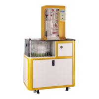
The VAPODEST 50 distillation system comes fully pre-assembled. Please unpack the equipment
with care !
1. Place the equipment on the work bench. Ideally, the equipment should be set up under con-
stant light conditions. This ensures that the contrast of the display does not have to be adju-
sted all the time. Be aware that direct sunlight on your screen has a negative influence on the
quality of your display.
2. Unpack accessories.
4.3. Tubing connections
When connecting the tubings please observe the inscription on the connection pipes at the back of
the equipment (see also chapter 3.2. "Rear View" and chapter 14. "Tubing Diagram")
1. Connect the pump tubes to the PVC-pipes of the store tanks:
- Inlet tubing sodium hydroxide (PVC-tubing 8/12)
- Inlet tubing for distilled water steam generator (PVC-tubing 4/7)
- Inlet tubing for distilled water sample (PVC-tubing 4/7)
- Inlet tubing for H
3
BO
3
(PVC-tubing 4/7)
- Connection tubing for titration acid to microdosing pump
2. Connect water inlet tubing (pressure proof tissue tubing 10/17) to cooling water inlet and labor-
atory water supply.
3. Connect outlet tubing:
- Connect water outlet tubing (PVC-tubing 8/12) to corresponding pipe at the rear of the equip-
ment and place in the drain.
- Connect sample waste outlet (Verprene tube 8/12) to corresponding pipe at the rear and direct
to sample waste tank.
- Connect outlet (PVC-tubing 8/12) to corresponding pipe at the rear of the equipment and place
in the drain.
4.4. Connection of the electrode
1. Take off the upper screw cap and the lower porous frit protection cap - please look for instruc-
tions inside of the electrode box. Now, connect the electrode to the cable and carefully introdu-
ASSEMBLY AND INSTALLATION