Home
GESTRA
Controller
NRR 2-52
Page 37 (Status Display of the NRR 2-52, NRR 2-53)
GESTRA NRR 2-52 - Status Display of the NRR 2-52, NRR 2-53
68 pages
Manual
Save Page as PDF
To Next Page
To Next Page
To Previous Page
To Previous Page
Loading...
37
NRR 2-52,
NRR 2-53,
URB 55 - USA- Installation & Operating Manual -
850698-00
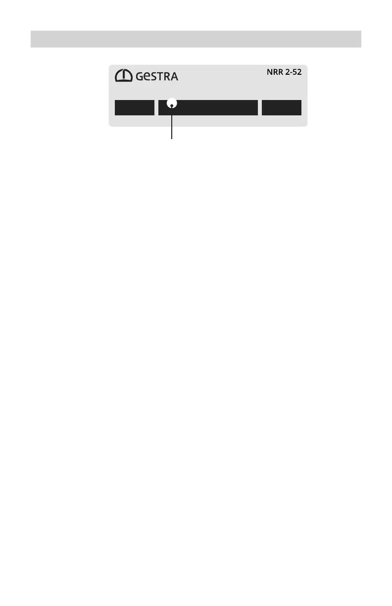
Status display of the NRR 2-52,
NRR 2-53
Fig.
21
Multicolor LED (amber/green/red),
amber = power up/green = running/red = malfunction
36
38
Table of Contents
Main Page
Table of Contents
2
Content of this Manual
5
Scope of Supply, Product Package
5
How to Use this Manual
6
Illustrations and Symbols Used
6
Hazard Symbols in this Manual
6
Types of Warning
7
Specialist Terms, Abbreviations
8
Usage for the Intended Purpose
9
IT Security and Rules for the Use of Ethernet Devices
10
Applicable Directives and Standards - NRR 2-52, NRR 2-53
10
Applicable Directives and Standards - URB 55
11
Improper Use
11
Basic Safety Information
12
Required Personnel Qualifications
12
Notes on Product Liability
12
Function
13
Possible Combinations of Functions and Equipment
13
Technical Data of the NRR 2-52, NRR 2-53
15
Technical Data of the URB 55
17
Factory Default Settings of the NRR 2-52, NRR 2-53
19
Nrr 2-52
19
Nrr 2-53
19
Nrr 2-52, Nrr 2-53
19
Factory Default Settings of the URB 55
20
Rating Plate, Identification of the NRR 2-52
21
Rating Plate, Identification of the NRR 2-53
22
Rating Plate, Identification of the URB 55
23
Functional Elements and Dimensions of the NRR 2-52, NRR 2-53
24
Installing the NRR 2-52, NRR 2-53 Level Controller
25
Dimensions of the URB 55
26
Required Installation Aperture in the Control Cabinet Door or Switch Panel
26
Installing the URB 55
27
Connecting the URB 55
28
Ports and Sockets on the Back of the Unit
28
Connection for 24 V DC Supply Voltage - Pin Assignment
28
Pin Assignment of Data Line between URB 55 and NRR 2-52, NRR 2-53
28
Safety Information for Electrical Connection of the Level Controller
29
Wiring Diagram of the NRR 2-52 Level Controller
30
Wiring Diagram of the NRR 2-53 Level Controller
31
Electrical Connection of the NRR 2-52, NRR 2-53
32
Connecting the 24 V DC Power Supply
32
Connecting the Output Contacts
32
Notes on Connecting Inductive Loads
32
Connecting the Level Electrode/Level Transmitter
32
Connecting the Actual Value Output OUT1 and Analog Output OUT2 (4 - 20 Ma)
32
Connecting the Digital Input (Terminals 29/30)
32
Connecting the Potentiometer (0 - 1000 W)
32
Connecting the Data Line between the Level Controller and the URB 55
33
Connecting the Spectormodul System
33
Changing the Equipment Settings
34
Setting the Measuring Range
36
Setting the Measuring Range for the NRGT 26-2 Level Transmitter
36
Status Display of the NRR 2-52, NRR 2-53
37
Visual Display and Operating Unit URB 55
38
Switching on the Supply Voltage
38
Operation and Navigation
39
User Interface (Example)
39
Color Coding of Input and Status Fields
39
Automatic Functions
40
Entering Parameters Using the Virtual Keypad
40
Entering Parameters with Password Protection
41
Scroll Bar for Long Lists and Menus
41
Icons and Functions of the NRR 2-52, NRR 2-53
42
Home Screen of NRR 2-52, NRR 2-53 Level Controllers
45
Alarm and Fault Indications
46
Opening the Alarm History
47
System Settings
48
System Information
48
Setting the Date/Time
49
Password
49
Network Settings
50
Data Exchange Via Modbus TCP
50
VNC Server / Remote Software
51
Configuring the Level Controller
52
Setting the MIN/MAX Switchpoints and Set Point
52
Automatic/Manual Mode
53
Trend Log
54
Test - Testing the Relays of the Connected Level Controller
55
Valve Calibration in Manual Mode When a Feedback Potentiometer Is Connected
56
Pump Control
57
Calibrate the Boiler Level (for NRG2
58
Setting the Level Controller
59
Guide to Setting Control Parameters
59
Setting the Level Controller for 3-Element Control
60
System Malfunctions in the URB 55
61
Indication of System Malfunctions in the Alarm and Error List Using Error Codes
61
Common Faults and Issues During Use of the URB 55
62
System Malfunctions in the NRR 2-52, NRR 2-53
63
Causes
63
Check the Installation and Configuration before Systematic Troubleshooting
63
What to Do in the Event of System Malfunctions
64
Checking Installation and Function
64
Taking the NRR 2-52, NRR 2-53 out of Service
64
Taking out of Service URB 55
64
UL Components
65
Disposal
65
Other manuals for GESTRA NRR 2-52
Installation & Operating Manual
68 pages
Original Installation Instructions
40 pages
Related product manuals
GESTRA NRR 2-40
40 pages
GESTRA NRS 1-9
40 pages
GESTRA LRR 1-50
36 pages
GESTRA LRR 1-52
72 pages
GESTRA LRGT 16-1
72 pages
GESTRA LRGT 16-2
72 pages
GESTRA LRGT 17-1
72 pages
GESTRA URB 55
72 pages
GESTRA LRR 1-5
8 pages
GESTRA URB 50
44 pages


 To Next Page