13
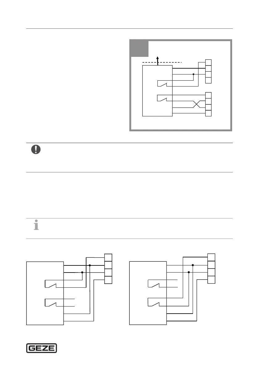
Special installation situationsGC 342 safety sensor
X
Cut the door transmission
cable to the correct length.
X
Strip the 8 wires and connect
them in accordance with the
wiring diagram.
X
Heed the polarity of the power
supply.
-UB
+UB
COM
+
SIO
60 mA
Test
SIS
GC 342
BGS
BN
GN
YE
WH
PK
GY
BU
RD
SIO
13
1
GND
2/4
2/4
24V
10
TST
SIO
SIS
11
1
GND
24V
10
TST
SIS
GC 342
BS
3
à For compliance with EN16005 and DIN18650, the test output of the door
control must be wired and able to test the sensor.
à The sensor is tested with GND.
X
Disable ECO-mode for connection to a GEZE Powerturn.
7 Special installation situations
7.1 Installation on re protection doors/glass doors
If a cable cannot be routed through the door, both sensors are connected
individually to the door control.
X
Use GC342 accessories.
SIO
13
1
GND
2/4
24V
10
TST
-UB
+UB
COM
+
SIO
60 mA
Test
SIS
GC 342
BN
GN
YE
WH
PK
GY
BU
RD
SIS
11
1
GND
2/4
24V
10
TST
-UB
+UB
COM
+
SIO
60 mA
Test
SIS
BN
GN
YE
WH
PK
GY
BU
RD

 Loading...